TA790GX3 A2+ Setup Manual FCC Information and Copyright This equipment has been tested and found to comply with the limits of a Class B digital device, pursuant to Part 15 of the FCC Rules. These limits are designed to provide reasonable protection against harmful interference in a residential installation. This equipment generates, uses, and can radiate radio frequency energy and, if not installed and used in accordance with the instructions, may cause harmful interference to radio communications.
Table of Contents Chapter 1: Introduction ............................................................ 1 1.1 Before You Start ................................................................................ 1 1.2 Package Checklist ............................................................................. 1 1.3 Motherboard Features...................................................................... 2 1.4 Rear Panel Connectors ..................................................................... 4 1.
TA790GX3 A2+ CHAPTER 1: INTRODUCTION 1.1 BEFORE YOU START Thank you for choosing our product. Before you start installing the motherboard, please make sure you follow the instructions below: 1.2 Prepare a dry and stable working environment with sufficient lighting. Always disconnect the computer from power outlet before operation.
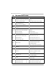
Motherboard Manual 1.3 MOTHERBOARD FEATURES SPEC AMD 64 Architecture enables 32 and 64 bit Socket AM2+ CPU AMD Athlon 64 / Athlon 64 FX / Athlon 64 X2 computing / Sempron / Phenom processors FSB Chipset Supports Hyper Transport 3.0 and PowerNow Support HyperTransport 3.0 Supports up to 5.2 GT/s Bandwidth AMD 790GX AMD SB750 ITE 8718 Environment Control initiatives, Provides the most commonly used legacy H/W Monitor Super I/O functionality.
TA790GX3 A2+ SPEC Floppy connector x1 Each connector supports 2 Floppy drives Printer Port connector x1 Each connector supports 1 Printer port IDE Connector x1 Each connector supports 2 IDE device SATA Connector x6 Each connector supports 1 SATA devices Front Panel Connector x1 Supports front panel facilities Front Audio Connector x1 Supports front panel audio function CD-in Connector x1 Supports CD audio-in function On Board S/PDIF out connector x1 Supports digital audio out functio
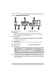
Motherboard Manual 1.4 X Z REAR PANEL CONNECTORS PS/2 Mouse Port Y PS/2 Keyboard Port HDMI Port The High-Definition Multimedia Interface (HDMI) is an all-digital audio/video interface capable of transmitting uncompressed streams to an AV receiver or any compatible digital audio and/or video monitor, such as a digital television.
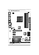
TA790GX3 A2+ 1.5 MOTHERBOARD LAYOUT JKBMS1 JCFAN1 JATXPWR3 JHDMI1 DIMMB2 DIMMA2 DIMMB1 DIMMA1 DVI VGA Socket AM2+ JATXPWR2 JUSB1 JUSBLAN1 IDE1 JAUDIO2 AMD 790GX J ATXPWR1 JUSBV1 JNFAN1 PEX16_1 LAN SATA4 SATA5 SATA6 PEX1_1 AMD SB750 PEX1_2 SATA3 SATA2 SATA1 LED_D1 LED_D2 PEX16_2 Codec BAT1 PCI1 BIOS JCMOS1 Super I/O JSPDIF_IN1 FDD1 PCI2 JAUDIOF1 JSPDIF_OUT1 JPRNT1 J COM1 JUSBV2 JCDIN1 JUSB5 JUSB3 J USB4 JSFAN1 JPANEL1 RSTSW1 PWRSW1 Note: ■ represents the 1st pin.
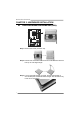
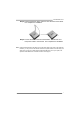
Motherboard Manual CHAPTER 2: HARDWARE INSTALLATION 2.1 INSTALLING CENTRAL PROCESSING UNIT (CPU) Step 1: Remove the socket protection cap. Step 2: Pull the lever toward direction A from the socket and then raise the lever up to a 90-degree angle. Step 3: Look for the white triangle on socket, and the gold triangle on CPU should point towards this white triangle. The CPU will fit only in the correct orientation.
TA790GX3 A2+ Step 4: Hold the CPU down firmly, and then close the lever toward direct B to complete the installation. Step 5: Put the CPU Fan on the CPU and buckle it. Connect the CPU FAN power cable to the JCFAN1. This completes the installation. Note: Please update the BIOS to the latest version while using AM2+ CPUs. Due to the latest CPU transition, you may encounter the situation that the new system failed to boot while using new AM2+ CPUs.
Motherboard Manual 2.2 FAN HEADERS These fan headers support cooling-fans built in the computer. The fan cable and connector may be different according to the fan manufacturer. Connect the fan cable to the connector while matching the black wire to pin#1.
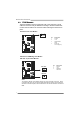
TA790GX3 A2+ 2.3 INSTALLING SYSTEM MEMORY DIMMB2 DIMMA2 DIMMB1 DIMMA1 A. DDR2 Modules 1. Unlock a DIMM slot by pressing the retaining clips outward. Align a DIMM on the slot such that the notch on the DIMM matches the break on the Slot. 2. Insert the DIMM vertically and firmly into the slot until the retaining chip snap back in place and the DIMM is properly seated.
Motherboard Manual B. Memory Capacity DIMM Socket Location Total Memory Size DDR2 Module DIMMA1 256MB/512MB/1GB/2GB/4GB DIMMB1 256MB/512MB/1GB/2GB/4GB DIMMA2 256MB/512MB/1GB/2GB/4GB DIMMB2 256MB/512MB/1GB/2GB/4GB Max is 16GB. C. Dual Channel Memory installation To trigger the Dual Channel function of the motherboard, the memory module must meet the following requirements: Install memory module of the same density in pairs, shown in the following table.
TA790GX3 A2+ 2.4 CONNECTORS AND SLOTS FDD1: Floppy Disk Connector The motherboard provides a standard floppy disk connector that supports 360K, 720K, 1.2M, 1.44M and 2.88M floppy disk types. This connector supports the provided floppy drive ribbon cables. 2 34 1 33 IDE1: IDE/ATAPI Connector The motherboard has a 32-bit Enhanced IDE Controller that provides PIO Mode 0~4, Bus Master, and Ultra DMA 33/66/100/133 functionality.
Motherboard Manual PEX16_1: PCI-Express Gen2 x16 Slot (x16/x8 Speed) - - - - PCI-Express 2.0 compliant. PCI-Express Gen2 supports a raw bit-rate of 5.0Gb/s on the data pins. 2X bandwidth over the PCI-Express 1.1 architecture. x16 Speed Mode: Maximum theoretical realized bandwidth of 8GB/s simultaneously per direction, for an aggregate of 16GB/s totally. (PEX16_2 must not be occupied.
TA790GX3 A2+ PEX1_1/PEX1_2: PCI-Express Gen2 x1 Slots - PCI-Express 2.0 compliant. Data transfer bandwidth up to 500MB/s per direction; 1GB/s in total. PCI-Express Gen2 supports a raw bit-rate of 5.0Gb/s on the data pins. 2X bandwidth over the PCI-Express 1.1 architecture. PEX1_ 1 PE X1_ 2 PCI1~PCI2: Peripheral Component Interconnect Slots This motherboard is equipped with 2 standard PCI slots. PCI stands for Peripheral Component Interconnect, and it is a bus standard for expansion cards.
Motherboard Manual CHAPTER 3: HEADERS & JUMPERS SETUP 3.1 HOW TO SETUP JUMPERS The illustration shows how to set up jumpers. When the jumper cap is placed on pins, the jumper is “close”, if not, that means the jumper is “open”. Pin opened 3.2 Pin closed Pin1-2 closed DETAIL SETTINGS JPANEL1: Front Panel Header This 16-pin connector includes Power-on, Reset, HDD LED, Power LED, and speaker connection. It allows user to connect the PC case’s front panel switch functions.
TA790GX3 A2+ JATXPWR2: ATX Power Source Connector This connector allows user to connect 24-pin power connector on the ATX power supply. Pin 13 14 15 16 17 18 19 20 21 22 23 24 12 24 1 13 Assignment +3.3V -12V Ground PS_ON Ground Ground Ground NC +5V +5V +5V Ground Pin 1 2 3 4 5 6 7 8 9 10 11 12 Assignment +3.3V +3.3V Ground +5V Ground +5V Ground PW_OK Standby Voltage+5V +12V +12V +3.3V JATXPWR3: ATX Power Source Connector By connecting this connector, it will provide +12V to CPU power circuit.
Motherboard Manual JATXPWR1: Auxiliary Power for Graphics This connector is an auxiliary power connection for graphics cards. Exclusive power for the graphics card provides better graphics performance. Pin 1 4 1 2 3 4 Assignment +12V Ground Ground VCC JCMOS1: Clear CMOS Header By placing the jumper on pin2-3, it allows user to restore the BIOS safe setting and the CMOS data, please carefully follow the procedures to avoid damaging the motherboard. 1 3 Pin 1-2 Close: Normal Operation (default).
TA790GX3 A2+ SATA1~SATA6: Serial ATA Connectors The motherboard has a PCI to SATA Controller with 6 channels SATA interface, it satisfies the SATA 2.0 spec and with transfer rate of 3.0Gb/s. SATA4 SATA5 SATA6 SATA3 SATA2 SATA1 7 4 Pin 1 2 3 4 5 6 7 Assignment Ground TX+ TXGround RXRX+ Ground 1 JUSB3~JUSB5: Headers for USB 2.0 Ports at Front Panel This header allows user to connect additional USB cable on the PC front panel, and also can be connected with internal USB devices, like USB card reader.
Motherboard Manual JAUDIOF1: Front Panel Audio Header This header allows user to connect the front audio output cable with the PC front panel. This header allows only HD audio front panel connector; AC’97 connector is not acceptable. 2 10 1 9 Pin 1 2 3 4 5 6 7 8 9 10 Assignment Mic Left in Ground Mic Right in GPIO Right line in Jack Sense Front Sense Key Left line in Jack Sense JSPDIF_OUT1: Digital Audio-out Connector This connector allows user to connect the PCI bracket SPDIF output header.
TA790GX3 A2+ JCDIN1: CD-ROM Audio-in Connector This connector allows user to connect the audio source from the variaty devices, like CD-ROM, DVD-ROM, PCI sound card, PCI TV turner card etc. Pin 1 2 3 4 1 Assignment Left Channel Input Ground Ground Right Channel Input 4 JPRNT1: Printer Port Connector This header allows you to connector printer on the PC.
Motherboard Manual JCOM1: Serial port Connector The motherboard has a Serial Port Connector for connecting RS-232 Port. 2 10 1 9 Pin 1 2 3 4 5 6 7 8 9 10 Assignment Carrier detect Received data Transmitted data Data terminal ready Signal ground Data set ready Request to send Clear to send Ring indicator NC JUSBV1/JUSBV2: Power Source Headers for USB Ports Pin 1-2 Close: JUSBV1: +5V for USB ports at JUSB1/JUSBLAN1. JUSBV2: +5V for USB ports at JUSB3/JUSB4/JUSB5.
TA790GX3 A2+ On-Board LED Indicators There are 2 LED indicators on the motherboard to show system status. LED_D1 LED_D2 LED_D1 and LED_D2: These 2 LED indicate system power on diagnostics. Please refer to the table below for different messages: LED_D2 OFF OFF ON ON LED_D1 OFF ON OFF ON Message Abnormal: CPU / Chipset error. Memory Error VGA Error Normal On-Board Buttons There are 2 on-board buttons. RSTSW1 PWRSW1 PWRSW1: This is an on-board Power Switch button.
Motherboard Manual CHAPTER 4: (HYBRID) CROSSFIREX FUNCTION 4.1 CROSSFIREX REQUIREMENTS Only Windows XP/Vista supports CrossFireX (Dual Video) function. A pair of graphics cards with Radeon HD3650/HD3850/HD3870/HD4850/ HD4870/HD3870X2 GPU. The graphics card driver should support CrossFireX technology. The power supply unit must provide at least the minimum power required by the system, or the system will be unstable. A power supply above 500W is recommended under CrossFireX mode. 4.
TA790GX3 A2+ 4.3 HYBRID CROSSFIREX REQUIREMENTS Only Windows Vista supports Hybrid CrossFireX function. A graphics card with Radeon HD3450/HD3470 GPU. The graphics card driver should support Hybrid CrossFireX technology. The power supply unit must provide at least the minimum power required by the system, or the system will be unstable. A power supply above 450W is recommended under Hybrid CrossFireX mode. 4.
Motherboard Manual 4.5 OPERATION MODES SUPPORTING LIST Operation Mode Single Card CrossFireX Hybrid CrossFireX Radeon HD3650 O O X Radeon HD3850 O O X Radeon HD3870 O O X Radeon HD4850 O O X Radeon HD4870 O O X Radeon HD3870X2 O O X Radeon HD3450 O X O Radeon HD3470 O X O Model (O means Supported, X means Not Supported.
TA790GX3 A2+ CHAPTER 5: RAID FUNCTIONS 5.1 OPERATION SYSTEM Supports Windows XP and Windows VISTA. 5.2 RAID ARRAYS RAID supports the following types of RAID arrays: RAID 0: RAID 0 defines a disk striping scheme that improves disk read and write times for many applications. RAID 1: RAID 1 defines techniques for mirroring data. RAID 1+0: RAID 1+0 combines the techniques used in RAID 0 and RAID 1. RAID 5: RAID 5 provides fault tolerance and better utilization of disk capacity. 5.
Motherboard Manual RAID 1: Every read and write is actually carried out in parallel across 2 disk drives in a RAID 1 array system. The mirrored (backup) copy of the data can reside on the same disk or on a second redundant drive in the array. RAID 1 provides a hot-standby copy of data if the active volume or drive is corrupted or becomes unavailable because of a hardware failure.
TA790GX3 A2+ RAID 1+0: RAID 1 drives can be stripped using RAID 0 techniques. Resulting in a RAID 1+0 solution for improved resiliency, performance and rebuild performance. Features and Benefits Drives: Minimum 4, and maximum is 6 or 8, depending on the platform. Benefits: Optimizes for both fault tolerance and performance, allowing for automatic redundancy. May be simultaneously used with other RAID levels in an array, and allows for spare disks.
Motherboard Manual RAID 5: RAID 5 stripes both data and parity information across three or more drives. It writes data and parity blocks across all the drives in the array. Fault tolerance is maintained by ensuring that the parity information for any given block of data is placed on a different drive from those used to store the data itself. Features and Benefits Drives: Minimum 3. Uses: RAID 5 is recommended for transaction processing and general purpose service.
TA790GX3 A2+ CHAPTER 6: T-SERIES BIOS & SOFTWARE 6.1 T-SERIES BIOS T-Series BIOS Features Overclocking Navigator Engine (O.N.E.) Memory Integration Test (M.I.T., under Overclock Navigator Engine) BIO-Flasher: Update BIOS file from USB Flash Drive or FDD Self Recovery System (S.R.S) Smart Fan Function CMOS Reloading Program !! WARNING !! For better system performance, the BIOS firmware is being continuously updated.
Motherboard Manual Manual Overclock System (M.O.S.) MOS is designed for experienced overclock users. It allows users to customize personal overclock settings. Main Advanced PCIPnP BIOS SETUP UTILITY Boot Chipset T-Series T-Series Settings Exit Options WARNING: Setting wrong values in below sections may cause system to malfunction.
TA790GX3 A2+ Hyper Transport Configuration Enter this function for more advanced Hyper Transport settings. Memory Configuration Enter this function for more advanced memory settings. EC Configuration Enter this function for more advanced Embedded Controller settings. GFX Engine Clock Override This item allows control the GFX Engine Clock. NOTE Overclock is an optional process, but not a “must-do” process; it is not recommended for inexperienced users.
Motherboard Manual V6 Tech Engine This engine will make a good over-clock performance. Main Advanced PCIPnP BIOS SETUP UTILITY Boot Chipset T-Series T-Series Settings Exit Options WARNING: Setting wrong values in below sections may cause system to malfunction.
TA790GX3 A2+ Notices: Not all types of AMD CPU perform above overclock setting ideally; the difference will be based on the selected CPU model. B. Memory Integration Test (M.I.T.) This function is under “Overclocking Navigator Engine” item. MIT allows users to test memory compatibilities, and no extra devices or software are needed. Step 1 The default setting under this item is “Disabled”; the condition parameter should be changed to “Enable” to proceed this test.
Motherboard Manual C. BIO-Flasher BIO-Flasher is a BIOS flashing utility providing you an easy and simple way to update your BIOS via USB pen drive or floppy disk. The BIO-Flasher is built in the BIOS chip. To enter the utility, press during the Power-On Self Tests (POST) procedure while booting up. Updating BIOS with BIO-Flasher 1. Go to the website to download the latest BIOS file for the motherboard. 2. Then, save the BIOS file into a USB pen drive or a floppy disk. 3.
TA790GX3 A2+ D. Self Recovery System (S.R.S.) This function can’t be seen under BIOS setup; and is always on whenever the system starts up. However, it can prevent system hang-up due to inappropriate overclock actions. When the system hangs up, S.R.S. will automatically log in the default BIOS setting, and all overclock settings will be re-configured. E. Smart Fan Function Smart Fan Function is under “Smart Fan Configuration” in “Advanced Menu”.
Motherboard Manual Smart Fan Calibration Choose this item and then the BIOS will automatically test and detect the CPU/System fan functions and show CPU/System fan speed. Control Mode This item provides several operation modes of the fan. Fan Ctrl OFF(℃) If the CPU/System temperature is lower than the set value, the CPU/ System fan will turn off. The range is from 0~127, with an interval of 1. Fan Ctrl On(℃) The CPU/System fan starts to work when CPU/System temperature arrives to this set value.
TA790GX3 A2+ 6.2 T-SERIES SOFTWARE Installing T-Series Software 1. Insert the Setup CD to the optical drive. The drivers installation program would appear if the Auto-run function has been enabled. 2. Select Software Installation, and then click on the respective software title. 3. Follow the on-screen instructions to complete the installation.
Motherboard Manual Over Clock Panel Restore Default Settings AUTO Over-Clock V3/V6/V9 Engine Real-time Ove r-clock Manual Adjust CPU Clock Test & Apply Manual Setting s AUTO User can click this button and the utility will set the best and stable performance and frequency automatically. A warning dialog as below will show up to notify you that the system may become unstable, click on “OK” to continue.
TA790GX3 A2+ Then the utility will execute a series of testing until system fail. Then system will do fail-safe reboot by using Watchdog function. After reboot, launch the utility again and the utility will load the previously verified best and stable frequency. V3 / V6 / V9 Provide user the ability to do real-time over-clock adjustment. For beginners in over-clock field, this is a powerful feature to increase system performance. V3 Engine This engine will make a good over-clock performance.
Motherboard Manual Over Voltage Panel Manual Adjust CPU/Memo ry/Chipset/FSB Voltage CPU Voltage This function allows user to adjust CPU voltage. or “-“ to decrease the CPU voltage. Memory Voltage This function allows user to adjust Memory voltage. increase or “-“ to decrease the Memory voltage. Click on “+” to Chip Voltage This function allows user to adjust Chipset voltage. increase or “-“ to decrease the Chipset voltage. Click on “+” to FSB Voltage This function allows user to adjust FSB voltage.
TA790GX3 A2+ About Panel In this panel, you can get model name and other system information that may related to over-clocking. You can also get the version number of this software. Note Because the Over Clock and Over Voltage features are controlled by several separate chipset, the utility divides these features to separate panels. If one chipset is not on board, the correlative button in Main panel will be disabled, but it will not interfere with other panels’ functions.
Motherboard Manual eHot-Line (Optional) eHot-Line is a convenient utility that helps you to contact with our Tech-Support system. This utility will collect the system information which is useful for analyzing the problem you may have encountered, and then send these information to our tech-support department to help you fix the problem. Before you use this utility, please set Outlook Express as your default e-mail client application program. represent s import ant *information that you must provide.
TA790GX3 A2+ Enter the file name and then click “Save”. Your system information will be saved to a .txt file. Open the saved .txt file, you will see your system information including motherboard/BIOS/CPU/video/ device/OS information. This information is also concluded in the sent mail. We will not share customer’s data with any other third parties, so please feel free to provide your system information while using eHot-Line service.
Motherboard Manual BIOS Update BIOS Update is a convenient utility which allows you to update your motherboard BIOS under Windows system. AWARD BIOS Show current BIOS information AMI BIOS Online Update function Clear CMOS function (Only for AMI BIOS) (Only for AWARD BIOS) Save current BIOS to a .bin file Update BIOS with a BIOS file Once click on this button, the saving dialog will show. Choose the position to save file and enter file name.
TA790GX3 A2+ Before doing this, please download the proper BIOS file from the website. For AWARD BIOS, update BIOS procedure should be run with Clear CMOS function, so please check on Clear CMOS first. Then click Update BIOS button, a dialog will show for asking you backup current BIOS. Click Yes for BIOS backup and refer to the Backup BIOS procedure; or click No to skip this procedure.
Motherboard Manual (for AMI BIOS only) Automatically download and update the latest BIOS via internet; make sure that the computer is connected to the internet before using this function. After clicking on the Onlinr Update button, the utility will search for the latest BIOS from internet. If there is a new BIOS version, the utility will ask you to download it. Click Yes to proceed.
TA790GX3 A2+ CHAPTER 7: USEFUL HELP 7.1 DRIVER INSTALLATION NOTE After you installed your operating system, please insert the Fully Setup Driver CD into your optical drive and install the driver for better system performance. You will see the following window after you insert the CD The setup guide will auto detect your motherboard and operating system. Note: If this window didn’t show up after you insert the Driver CD, please use file browser to locate and execute the file SETUP.
Motherboard Manual 7.2 EXTRA INFORMATION CPU Overheated If the system shutdown automatically after power on system for seconds, that means the CPU protection function has been activated. When the CPU is over heated, the motherboard will shutdown automatically to avoid a damage of the CPU, and the system may not power on again. In this case, please double check: 1. The CPU cooler surface is placed evenly with the CPU surface. 2. CPU fan is rotated normally. 3.
TA790GX3 A2+ 7.3 AMI BIOS BEEP CODE Boot Block Beep Codes Number of Beeps 1 2 3 4 5 7 10 11 12 13 Description No media present. (Insert diskette in floppy drive A:) “AMIBOOT.ROM” file not found in root directory of diskette in A: Insert next diskette if multiple diskettes are used for recovery Flash Programming successful File read error No Flash EPROM detected Flash Erase error Flash Program error “AMIBOOT.
Motherboard Manual 7.4 TROUBLESHOOTING Probable 1. Solution No power to the system at all 1. Make sure power cable is Power light don’t illuminate, fan securely plugged in. inside power supply does not turn 2. Replace cable. on. 3. Contact technical support. 2. Indicator light on keyboard does not turn on. System inoperative. Keyboard lights Using even pressure on both ends of are on, power indicator lights are lit, the DIMM, press down firmly until the and hard drive is spinning.
TA790GX3 A2+ This page is intentionally left blank.
Motherboard Manual APPENDIX: SPEC IN OTHER LANGUAGE GERMAN Spezifikationen CPU FSB Chipsatz Sockel AM2+ Die AMD 64-Architektur unterstützt eine 32-Bit- und AMD Athlon 64 / Athlon 64 FX / Athlon 64 64-Bit-Datenverarbeitung X2 / Sempron / Phenom Prozessoren Unterstützt Hyper Transport 3.0 und PowerNow Unterstützt HyperTransport 3.0 mit einer Bandbreite von bis zu 5.
TA790GX3 A2+ Spezifikationen Diskettenlaufwerkanschluss x1 Jeder Anschluss unterstützt 2 Diskettenlaufwerke Druckeranschluss Anschluss x1 Jeder Anschluss unterstützt 1 Druckeranschluss IDE-Anschluss x1 Jeder Anschluss unterstützt 2 IDE-Laufwerke SATA-Anschluss x6 Jeder Anschluss unterstützt 1 SATA-Laufwerk Fronttafelanschluss x1 Unterstützt die Fronttafelfunktionen Front-Audioanschluss x1 Unterstützt die Fronttafel-Audioanschlussfunktion CD-IN-Anschluss x1 Unterstützt die CD Audio-In-Fun
Motherboard Manual FRANCE SPEC Socket AM2+ UC Processeurs AMD Athlon 64 / Athlon 64 FX / Athlon 64 X2 / Sempron / Phenom Bus frontal Chipset Super E/S L'architecture AMD 64 permet le calcul 32 et 64 bits Prend en charge Hyper Transport 3.0 et PowerNow Prend en charge Hyper Transport 3.0 jusqu'à une bande passante de 5.2 GT/s AMD 790GX AMD SB750 ITE 8718 Initiatives de contrôle environnementales, Fournit la fonctionnalité de Super E/S Moniteur de matériel patrimoniales la plus utilisée.
TA790GX3 A2+ SPEC Connecteur IDE x1 Chaque connecteur prend en charge 2 périphériques IDE Chaque connecteur prend en charge 1 périphérique Connecteur SATA x6 Connecteur du panneau avant x1 Prend en charge les équipements du panneau avant Connecteur Audio du panneau avant x1 Prend en charge la fonction audio du panneau avant Connecteur d'entrée CD x1 Prend en charge la fonction d'entrée audio de CD Connecteur de sortie S/PDIF x1 Connecteur d'entrée S/PDIF x1 Embase de ventilateur UC x1 Emb
Motherboard Manual ITALIAN SPECIFICA Socket AM2+ CPU Processori AMD Athlon 64 / Athlon 64 FX / Athlon 64 X2 / Sempron / Chipset Supporto di HyperTransport 3.0 fino a 5.2 GT/s di larghezza di banda AMD 790GX AMD SB750 Funzioni di controllo dell’ambiente: ITE 8718 Super I/O Fornisce le funzionalità legacy Super Monitoraggio hardware I/O usate più comunemente.
TA790GX3 A2+ SPECIFICA Connettore pannello frontale x1 Supporta i servizi del pannello frontale Connettore audio frontale x1 Supporta la funzione audio pannello frontale Connettore CD-in x1 Supporta la funzione input audio CD Connettore output S/PDIF x1 Supporta la funzione d’output audio digitale Connettore input S/PDIF x1 Supporta la funzione d’input audio digitale Collettore ventolina CPU x1 Collettore ventolina sistema x2 Collettore cancellaz ione CMOS x1 Connettore USB x3 Porta s
Motherboard Manual SPANISH Especificación La arquitectura AMD 64 permite el procesado de 32 y Conector AM2+ CPU Procesadores AMD Athlon 64 / Athlon 64 FX / Athlon 64 X2 / Sempron / Phenom FSB 64 bits Soporta las tecnologías Hyper Transport 3.0 y PowerNow Admite HyperTransport 3.0 con un ancho de banda de hasta 5.2 GT/s Conjunto de AMD 790GX chips AMD SB750 Iniciativas de control de entorno, ITE 8718 Súper E/S Le ofrece las funcionalidades heredadas de Monitor hardware uso más común Súper E/S.
TA790GX3 A2+ Especificación Conectores en placa Conector disco flexible X1 Cada conector soporta 2 unidades de disco flexible Conector Puerto de impresora X1 Cada conector soporta 1 Puerto de impresora Conector IDE X1 Cada conector soporta 2 dispositivos IDE Conector SATA X6 Cada conector soporta 1 dispositivos SATA Conector de panel frontal X1 Soporta instalaciones en el panel frontal Conector de sonido frontal X1 Soporta funciones de sonido en el panel frontal Conector de entrada de CD
Motherboard Manual PORTUGUESE ESPECIFICAÇÕES A arquitectura AMD 64 permite uma computação de 32 Socket AM2+ CPU Processadores AMD Athlon 64 / Athlon 64 FX / Athlon 64 X2 / Sempron / Phenom FSB Chipset o Super I/O principal PowerNow com uma largura de banda até 5.2 GT/s AMD 790GX AMD SB750 Iniciativas para controlo do ambiente Proporciona as funcionalidades mais utilizadas em termos da especificação Super I/O.
TA790GX3 A2+ ESPECIFICAÇÕES Conector do painel frontal x1 Para suporte de várias funções no painel frontal Conector de áudio frontal x1 Suporta a função de áudio no painel frontal Conector para entrada de CDs x1 Suporta a entrada de áudio a partir de CDs Conector de saída S/PDIF x1 Suporta a saída de áudio digital Conector de entrada S/PDIF x1 Suporta a entrada de áudio digital Conector da ventoinha da CPU x1 Conector da ventoinha do sistema x2 Conector para limpeza do CMOS x1 Conector
Motherboard Manual POLISH SPEC Procesor FSB Chipset Socket AM2+ Architektura AMD 64 umożliwia przetwarzanie AMD Athlon 64 / Athlon 64 FX / Athlon 64 X2 / 32 i 64 bitowe Sempron / Phenom Procesory Obsługa Hyper Transport 3.0 oraz PowerNow Obsługa HyperTransport 3.0 o szerokości pasma do 5.2 GT/s AMD 790GX AMD SB750 Moduł pamięci DDR2 z trybem podwójnego Gniazda DDR2 DIMM x 4 Pamięć Każde gniazdo DIMM obsługuje moduły główna 256MB/512MB/1GB/2GB/4GB DDR2 Maks.
TA790GX3 A2+ SPEC Złącze SATA x6 Złącze panela przedniego x1 Każde złącze obsługuje 1 urządzenie SATA Obsługa elementów panela przedniego Przednie złącze audio x1 Obsługa funkcji audio na panelu przednim Złącze wejścia CD x1 Obsługa funkcji wejścia audio CD Złącze wyjścia S/PDIF x1 Obsługa funkcji cyfrowego wyjścia audio Złącze wejścia S/PDIF x1 Obsługa funkcji cyfrowego wejścia audio x1 Fan) Złącze główkowe wentylatora procesora Zasilanie wentylatora procesora (z funkcją Smart Złącze g
Motherboard Manual RUSSIAN СПЕЦ CPU (центральн ый процессор) FSB Набор Архитектура AMD 64 разрешать обработка Гнездо AM2+ Процессоры AMD Athlon 64 / Athlon 64 FX / данных на 32 и 64 бит Athlon 64 X2 / Sempron / Phenom Поддержка Hyper Transport 3.0 и PowerNow Поддержка HyperTransport 3.0 с пропускной способностью до 5.
TA790GX3 A2+ СПЕЦ Разъём IDE x1 Каждый разъём поддерживает 2 встроенных интерфейса накопителей Разъём SATA x6 Каждый разъём поддерживает 1 устройство SATA Разъём на лицевой панели x1 Поддержка устройств на лицевой панели Входной звуковой разъём x1 Разъём ввода для CD x1 Поддержка функции ввода для CD Разъём вывода для S/PDIF x1 Поддержка вывода цифровой звуковой функции Разъём ввода для S/PDIF x1 Поддержка ввода цифровой звуковой функции Источник питания для вентилятора центрального Конт
Motherboard Manual ARABIC اﻟﻤﻮاﺻﻔﺎت وﺣﺪة اﻟﻤﻌﺎﻟﺠﺔ اﻟﻤﺮآﺰﻳﺔ اﻟﻨﺎﻗﻞ اﻷﻡﺎﻡﻲ اﻟﺠﺎﻥﺒﻲ ﻡﺠﻤﻮﻋﺔ اﻟﺸﺮاﺋﺢ AM2+ﻡﻘﺒﺲ AMD Athlon 64 / Athlon 64 FX / Athlon 64ﻡﻌﺎﻟﺠﺎت X2 / Sempron / Phenom PowerNowو Hyper Transport 3.0ﺗﺪﻋﻢ ﺗﻘﻨﻴﺔ 5.2 GT/sﺏﺘﺮدد ﻳﺼﻞ إﻟﻰ HyperTransport 3.
TA790GX3 A2+ اﻟﻤﻮاﺻﻔﺎت ﻡﻨﻔﺬ ﻡﺤﺮك أﻗﺮاص ﻡﺮﻥﺔ ﻋﺪد 1 ﻡﻨﻔﺬ ﻃﺎﺏﻌﺔ ﻋﺪد 1 ﻡﻨﻔﺬ IDE ﻋﺪد 1 IDEﻳﺪﻋﻢ آﻞ ﻡﻨﻔﺬ اﺙﻨﻴﻦ ﻡﻦ أﺝﻬﺰة ﻡﻨﻔﺬ SATA ﻋﺪد6 SATAﻳﺪﻋﻢ آﻞ ﻡﻨﻔﺬ واﺣﺪ ﻡﻦ أﺝﻬﺰة ﻳﺪﻋﻢ ﻡﺤﺮآﻴﻦ ﻟﻸﻗﺮاص اﻟﻤﺮﻥﺔ ﻡﻨﻔﺬ اﻟﻠﻮﺣﺔ اﻷﻡﺎﻡﻴﺔ ﻋﺪد 1 ﻳﺪﻋﻢ ﺗﺠﻬﻴﺰات اﻟﻠﻮﺣﺔ اﻷﻡﺎﻡﻴﺔ ﻡﻨﻔﺬ اﻟﺼﻮت اﻷﻡﺎﻡﻲ ﻋﺪد 1 ﻳﺪﻋﻢ وﻇﻴﻔﺔ اﻟﺼﻮت ﺏﺎﻟﻠﻮﺣﺔ اﻷﻡﺎﻡﻴﺔ ﻡﻨﻔﺬ CD-IN ﻋﺪد 1 ﻳﺪﻋﻢ وﻇﻴﻔﺔ دﺥﻞ ﺹﻮت اﻟﻘﺮص اﻟﻤﺪﻡﺞ اﻟﻤﻨﺎﻓﺬ ﻋﻠﻰ ﺳﻄﺢ ﻡﻨﻔﺬ ﺥﺮج S/PDIF ﻋﺪد 1 ﻳﺪﻋﻢ وﻇﻴﻔﺔ ﺥﺮج اﻟﺼﻮت اﻟﺮ
Motherboard Manual JAPANESE 仕様 AMD 64アーキテクチャでは、32ビットと64ビット計算が Socket AM2+ CPU AMD Athlon 64 / Athlon 64 FX / Athlon 64 X2 可能です ハイパートランスポート3.0とクールアンドクワイアット / Sempron / Phenom プロセッサ をサポートします FSB 5.2 GT/sのバンド幅までハイパートランスポート 3.
TA790GX3 A2+ 仕様 フロッピーコネクタ x1 各コネクタは2つのフロッピードライブをサポートします プリンタポートコネクタ x1 各コネクタは1つのプリンタポートをサポートします IDEコネクタ x1 各コネクタは2つのIDEデバイスをサポートします SATAコネクタ x6 各コネクタは1つのSATAデバイスをサポートします フロントパネルコネクタ x1 フロントパネル機能をサポートします フロントオーディオコネクタ x1 フロントパネルオーディオ機能をサポートします CDインコネクタ x1 CDオーディオイン機能をサポートします S/PDIFアウトコネクタ x1 デジタルオーディオアウト機能をサポートします S/PDIFインコネクタ x1 デジタルオーディオイン機能をサポートします CPUファンヘッダ x1 CPUファン電源装置(スマートファン機能を搭載) システムファンヘッダ x2 システムファン電源装置 CMOSクリアヘッダ x1 USBコネクタ x3 シリアルポート x1 電源コネクタ(24ピン) x1 電源