MCP6P3 Setup Manual FCC Information and Copyright This equipment has been tested and found to comply with the limits of a Class B digital device, pursuant to Part 15 of the FCC Rules. These limits are designed to provide reasonable protection against harmful interference in a residential installation. This equipment generates, uses, and can radiate radio frequency energy and, if not installed and used in accordance with the instructions, may cause harmful interference to radio communications.
Table of Contents Chapter 1: Introduction ............................................................ 3 1.1 Before You Start ....................................................................... 3 1.2 Package Checklist..................................................................... 3 1.3 Motherboard Features ............................................................. 4 1.4 1.5 Rear Panel Connectors ........................................................... 5 Motherboard Layout ..............
MCP6P3 CHAPTER 1: INTRODUCTION 1.1 BEFORE Y OU START Thank you for choosing our product. Before you start installing the motherboard, please make sure you follow the instructions below: Prepare a dry and stable working environment with sufficient lighting. Always disconnect the computer from power outlet before operation. Before you take the motherboard out from anti-static bag, ground yourself properly by touching any safely grounded appliance, or use grounded wrist strap to remove the static charge.
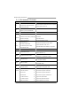
Motherboard Manual 1.3 MOTHERBOARD FEATURES SPEC Socket AM3 CPU AMD Phenom II/ Athlon II processors (Maximum Watt: 95W) FSB Chipset Supports up to 2.0 GT/s Bandwidth GeForce 6150 SE/nForce 430 Environment Control initiatives, Provides the most commonly used legacy H/W Monitor Super I/O functionality.
MCP6P3 SPEC CPU Fan Header Back Panel I/O Board Size Special Features x1 CPU Fan power supply (with Smart Fan function) System Fan Header x1 System Fan Power supply CMOS clear Header x1 Restore CMOS data to factory default USB Connector x3 Each connector supports 2 front panel USB ports Power Connector (24pin) x1 Connects to Power supply Power Connector (4pin) x1 Connects to Power supply PS/2 Keyboard x1 Connects to PS/2 Keyboard PS/2 Mouse x1 Connects to PS/2 Mouse VGA port x1 C
Motherboard Manual 1.5 MOTHERBOARD LAYOUT KBMS1 CPU_FAN1 ATXPWR2 JKB_PWR AM 3 DDR3_A1 S o c k et VGA 1 DDR3_B1 C OM 1 USB1 JUSBV1 ATXPWR1 JU SBV2 IDE1 RJ45USB1 AUDIO1 GeForce 6150 SE/ nForce430 F_AUDIO1 F_USB2 F_USB1 LAN PEX16_1 BIOS BAT1 JCMOS1 Super I/O PCI1 PCI2 Codec JPRI NT1 FDD1 JSPDIFOUT1 Note: ■ represents the 1st pin.
MCP6P3 CHAPTER 2: HARDWARE INSTALLATION 2.1 INSTALLING C ENTRAL PROCESSING UNIT (CPU) Step 1: Pull the lever toward direction A from the socket and then raise the lever up to a 90-degree angle. Step 2: Look for the white triangle on socket, and the gold triangle on CPU should point towards this white triangle. The CPU will fit only in the correct orientation.
Motherboard Manual Step 3: Hold the CPU down firmly, and then close the lever toward direct B to complete the installation. Step 4: Put the CPU Fan on the CPU and buckle it. Connect the CPU FAN power cable to the CPU_FAN1. This completes the installation.
MCP6P3 2.2 FAN HEADERS These fan headers support cooling-fans built in the computer. The fan cable and connector may be different according to the fan manufacturer. Connect the fan cable to the connector while matching the black wire to pin#1. CPU_FAN1: CPU Fan Header 1 4 Pin Assignment Ground +12V FAN RPM rate sense Smart Fan Control (By Fan) 1 2 3 4 SYS_FAN1: System Fan Header Pin 1 2 3 1 Assignment Ground +12V FAN RPM rate sense 3 Note: CPU_FAN1 supports 4-pin head connector.
Motherboard Manual 2.3 INSTALLING S YSTEM MEMORY D D R3 _A 1 D D R3 _B 1 A. Memory Modules 10 1. Unlock a DIMM slot by pressing the retaining clips outward. Align a DIMM on the slot such that the notch on the DIMM matches the break on the Slot. 2. Insert the DIMM vertically and firmly into the slot until the retaining chip snap back in place and the DIMM is properly seated.
MCP6P3 B. Memory Capacity DIMM Socket Location DDR3 Module Total Memory Size DDR3_A1 512MB/1GB/2GB/4GB DDR3_B1 512MB/1GB/2GB/4GB Max is 8GB. C. Dual Channel Memory installation Please refer to the following requirements to activate Dual Channel function: Install memory module of the same density in pairs, shown in the table. Dual Channel Status DDR3_A1 DDR3_B1 Disabled O X Disabled X O Enabled O O (O means memory installed, X means memory not installed.
Motherboard Manual 2.4 CONNECTORS AND S LOTS FDD1: Floppy Disk Connector The motherboard provides a standard floppy disk connector that supports 360K, 720K, 1.2M, 1.44M and 2.88M floppy disk types. This connector supports the provided floppy drive ribbon cables. 2 34 1 33 IDE1: IDE/ATAPI Connector The motherboard has a 32-bit Enhanced PCI IDE Controller that provides PIO Mode 0~4, Bus Master, and Ultra DMA 33/66/100/133 functionality.
MCP6P3 SATA1~SATA4: Serial ATA Connectors The motherboard has a PCI to SATA Controller with 4 channels SATA interface. Pin 1 2 3 4 5 6 7 S ATA2 S ATA4 S ATA1 S ATA3 1 4 Assignment Ground TX+ TXGround RXRX+ Ground 7 ATXPWR1: ATX Power Source Connector This connector allows user to connect 24-pin power connector on the ATX power supply. Pin 13 14 15 16 17 18 19 20 21 22 23 24 Assignment +3.
Motherboard Manual ATXPWR2: ATX Power Source Connector Connecting this connector provides +12V to CPU power circuit. 1 4 2 3 Pin 1 2 3 4 Assignment +12V +12V Ground Ground Note: Before you power on the system, please make sure that both ATXPWR1 and ATXPWR2 connectors have been plugged-in. PCI-EX16: PCI-Express x16 Slot - PCI-Express 1.0a compliant. Maximum theoretical realized bandwidth of 4GB/s simultaneously per direction, for an aggregate of 8GB/s totally.
MCP6P3 PCI1~PCI2: Peripheral Component Interconnect Slots This motherboard is equipped with 2 standard PCI slots. PCI stands for Peripheral Component Interconnect, and it is a bus standard for expansion cards. This PCI slot is designated as 32 bits.
Motherboard Manual CHAPTER 3: HEADERS & JUMPERS SETUP 3.1 HOW TO S ETUP JUMPERS The illustration shows how to set up jumpers. When the jumper cap is placed on pins, the jumper is “close”, if not, that means the jumper is “open”. Pin opened Pin closed Pin1-2 closed 3.2 DETAIL S ETTINGS PANEL1: Front Panel Header This 16-pin connector includes Power-on, Reset, HDD LED, Power LED, and speaker connection. It allows user to connect the PC case’s front panel switch functions.
MCP6P3 F_USB1/F_USB2: Headers for USB 2.0 Ports at Front Panel These headers allow user to connect additional USB cable on the PC front panel, and also can be connected with internal USB devices, like USB card reader.
Motherboard Manual F_AUDIO1: Front Panel Audio Header This header allows user to connect the front audio output cable with the PC front panel. This header allows only HD audio front panel connector; AC’97 connector is not acceptable. 2 10 1 9 Pin 1 2 3 4 5 6 7 8 9 10 Assignment Mic Left in Ground Mic Right in GPIO Right line in Jack Sense Front Sense Key Left line in Jack Sense JSPDIFOUT1: Digital Audio-out Connector This connector allows user to connect the PCI bracket SPDIF output header.
MCP6P3 J_PRINT1: Printer Port Connector This header allows you to connector printer on the PC.
Motherboard Manual JUSBV1/JUSBV2: Power Source Headers for USB Ports Pin 1-2 Close: JUSBV1: +5V for USB ports at USB1/RJ45USB1. JUSBV2: +5V for USB ports at F_USB1/F_USB2. Pin 2-3 Close: JUSBV1: +5V STB for USB ports at USB1/RJ45USB1. JUSBV2: +5V STB for USB ports at F_USB1/F_USB2. JUSBV1 3 1 3 1 Pin 1-2 close 3 1 JUSBV2 3 1 Pin 2-3 close JKB_PWR: Power Source Header for PS/2 Keyboard and Mouse 3 1 3 1 Pin 1-2 close +5V for PS/2 keyboard and mouse.
MCP6P3 CHAPTER 4: RAID FUNCTIONS 4.1 OPERATION SYSTEM Supports Windows XP, Windows Vista, and Windows 7. 4.2 RAID ARRAYS RAID supports the following types of RAID arrays: RAID 0: RAID 0 defines a disk striping scheme that improves disk read and write times for many applications. RAID 1: RAID 1 defines techniques for mirroring data. RAID 0+1: RAID 0+1 combines the techniques used in RAID 0 and RAID 1. RAID 5: RAID 5 provides fault tolerance and better utilization of disk capacity. 4.
Motherboard Manual RAID 1: Every read and write is actually carried out in parallel across 2 disk drives in a RAID 1 array system. The mirrored (backup) copy of the data can reside on the same disk or on a second redundant drive in the array. RAID 1 provides a hot-standby copy of data if the active volume or drive is corrupted or becomes unavailable because of a hardware failure.
MCP6P3 RAID 0+1: RAID 0 drives can be mirrored using RAID 1 techniques. Resulting in a RAID 0+1 solution for improved performance plus resiliency. Features and Benefits Drives: Minimum 4, and maximum is 6 or 8, depending on the platform. Benefits: Optimizes for both fault tolerance and performance, allowing for automatic redundancy. May be simultaneously used with other RAID levels in an array, and allows for spare disks.
Motherboard Manual RAID 5: RAID 5 stripes both data and parity information across three or more drives. It writes data and parity blocks across all the drives in the array. Fault tolerance is maintained by ensuring that the parity information for any given block of data is placed on a different drive from those used to store the data itself. Features and Benefits Drives: Minimum 3. Uses: RAID 5 is recommended for transaction processing and general purpose service.
MCP6P3 CHAPTER 5: USEFUL HELP 5.1 DRIVER I NSTALLATION NOTE After you installed your operating system, please insert the Fully Setup Driver CD into your optical drive and install the driver for better system performance. You will see the following window after you insert the CD The setup guide will auto detect your motherboard and operating system. Note: If this window didn’t show up after you insert the Driver CD, please use file browser to locate and execute the file SETUP.EXE under your optical drive.
Motherboard Manual 5.2 SOFTWARE Installing Software 1. Insert the Setup CD to the optical drive. The drivers installation program would appear if the Autorun function has been enabled. 2. Select Software Installation, and then click on the respective software title. 3. Follow the on-screen instructions to complete the installation. BIOScreen Utility This utility allows you to personalize your boot logo easily. You can choose JPG or BMP as your boot logo so as to customize your computer.
MCP6P3 5.3 AMI BIOS BEEP CODE Boot Block Beep Codes Number of Beeps 1 2 3 4 5 7 10 11 12 13 Description No media present. (Insert diskette in floppy drive A:) “AMIBOOT.ROM” file not found in root directory of diskette in A: Insert next diskette if multiple diskettes are used for recovery Flash Programming successful File read error No Flash EPROM detected Flash Erase error Flash Program error “AMIBOOT.
Motherboard Manual 5.4 EXTRA INFORMATION CPU Overheated If the system shutdown automatically after power on system for seconds, that means the CPU protection function has been activated. When the CPU is over heated, the motherboard will shutdown automatically to avoid a damage of the CPU, and the system may not power on again. In this case, please double check: 1. The CPU cooler surface is placed evenly with the CPU surface. 2. CPU fan is rotated normally. 3. CPU fan speed is fulfilling with the CPU speed.
MCP6P3 5.5 TROUBLESHOOTING Probable 1. There is no power in the system. Power LED does not shine; the fan of the power supply does not work 2. Indicator light on keyboard does not shine. System is inoperative. Keyboard lights are on, power indicator lights are lit, and hard drives are running. System does not boot from a hard disk drive, but can be booted from optical drive. System only boots from an optical drive.
Motherboard Manual APPENDIX: SPEC IN OTHER LANGUAGES GERMAN Spezifikationen CPU FSB Chipsatz Sockel AM3 Die AMD 64-Architektur unterstützt eine 32-Bit- und AMD Phenom II/ Athlon II Prozessoren 64-Bit-Datenverarbeitung (Maximales Watt: 95W) Unterstützt Hyper Transport 2.0 Unterstützt HyperTransport 2.0 mit einer Bandbreite von bis zu 2.0 GT/s GeForce 6150 SE/nForce 430 ITE 8718F Super E/A Umgebungskontrolle, Bietet die häufig verwendeten alten Super Hardware-Überwachung E/A-Funktionen.
MCP6P3 Spezifikationen Rückseiten-E /A Platinengröße .
Motherboard Manual FRENCH SPEC Socket AM3 UC Processeurs AMD Phenom II/ Athlon II (Watt maximum : 95W) Bus frontal Chipset L'architecture AMD 64 permet le calcul 32 et 64 bits Prend en charge Hyper Transport 2.0 Prend en charge Hyper Transport 2.0 jusqu'à une bande passante de 2.0 GT/s GeForce 6150 SE/nForce 430 ITE 8718F Initiatives de contrôle environnementales, Fournit la fonctionnalité de Super E/S Moniteur de matériel patrimoniales la plus utilisée.
MCP6P3 SPEC Chaque connecteur prend en charge 1 périphérique Connecteur SATA x4 Connecteur du panneau avant x1 Prend en charge les équipements du panneau avant Connecteur Audio du panneau avant x1 Prend en charge la fonction audio du panneau avant Connecteur de sortie S/PDIF x1 Prend en charge la fonction de sortie audio numérique Embase de ventilateur UC x1 Embase de ventilateur système x1 Embase d'effacement CMOS x1 Connecteur USB x3 Connecteur d'alimentation x1 SATA Alimentation éle
Motherboard Manual ITALIAN SPECIFICA CPU FSB Chipset Socket AM3 L’architettura AMD 64 abilita la co mputazione 32 Processori AMD Phenom II/ Athlon II e 64 bit (Watt massimo: 95W) Supporto di Hyper Transport 2.0 Supporto di HyperTransport 2.0 fino a 2.0 GT/s di larghezza di banda GeForce 6150 SE/nForce 430 ITE 8718F Super I/O Funzioni di controllo dell’ambiente: Fornisce le funzionalità legacy Super Monitoraggio hardware I/O usate più comunemente.
MCP6P3 SPECIFICA Connettore pannello frontale x1 Supporta i servizi del pannello frontale Connettore audio frontale x1 Supporta la funzione audio pannello frontale Connettore output SPDIF x1 Supporta la funzione d’output audio digitale Collettore ventolina CPU x1 Collettore ventolina sistema x1 Collettore cancellaz ione CMOS x1 Connettore USB x3 Connettore alimentazione x1 Alimentazione ventolina CPU (con funzione Smart Fan) Alimentazione ventolina di sistema Ciascun connettore supporta
Motherboard Manual SPANISH Especificación CPU FSB Conjunto de chips Conector AM3 La arquitectura AMD 64 permite el procesado de 32 y Procesadores AMD Phenom II/ Athlon II 64 bits (Vatio máximo: 95W) Soporta las tecnologías Hyper Transport 2.0 Admite HyperTransport 2.0 con un ancho de banda de hasta 2.0 GT/s GeForce 6150 SE/nForce 430 ITE 8718F Súper E/S Iniciativas de control de entorno, Le ofrece las funcionalidades heredadas de Monitor hardware uso más común Súper E/S.
MCP6P3 Especificación Conector de panel frontal X1 Soporta instalaciones en el panel frontal Conector de sonido frontal X1 Soporta funciones de sonido en el panel frontal Conector de salida S/PDIF X1 Soporta función de salida de sonido digital Cabecera de ventilador de CPU X1 Cabecera de ventilador de sistema X1 Cabecera de borrado de CMOS X1 Conector USB X3 Conector de alimentación X1 Fuente de alimentación de ventilador de CPU (con función Smart Fan) Fuente de alimentación de ventilador d
Motherboard Manual PORTUGUESE ESPECIFICAÇÕES A arquitectura AMD 64 permite uma computação de 32 Socket AM3 CPU Processadores AMD Phenom II/ Athlon II e 64 bits (Watt máximo: 95W) FSB Chipset Suporta as tecnologias Hyper Transport 2.0 Suporta a tecnologia HyperTransport 2.0 com uma largura de banda até 2.0 GT/s GeForce 6150 SE/nForce 430 ITE 8718F Especificaçã o Super I/O Iniciativas para controlo do ambiente Proporciona as funcionalidades mais utilizadas em termos da especificação Super I/O.
MCP6P3 ESPECIFICAÇÕES Conector do painel frontal x1 Para suporte de várias funções no painel frontal Conector de áudio frontal x1 Suporta a função de áudio no painel frontal Conector de saída S/PDIF x1 Suporta a saída de áudio digital Conector da ventoinha da CPU x1 Conector da ventoinha do sistema x1 Conector para limpeza do CMOS x1 Conector USB x3 Conector de alimentação x1 Alimentação da ventoinha da CPU (com a função Smart Fan) Alimentação da ventoinha do sistema Cada conector suport
Motherboard Manual POLISH SPEC Procesor FSB Chipset Socket AM3 Architektura AMD 64 umożliwia przetwarzanie 32 i 64 AMD Phenom II/ Athlon II Procesory bitowe (Maksymalny Watt: 95W) Obsługa Hyper Transport 2.0 Obsługa HyperTransport 2.0 o szerokości pasma do 2.0 GT/s GeForce 6150 SE/nForce 430 Gniazda DDR3 DIMM x 2 Moduł pamięci DDR3 z trybem podwójnego kanału Pamięć Maks.
MCP6P3 SPEC Przednie złącze audio x1 Obsługa funkcji audio na panelu przednim Złącze wyjścia S/PDIF x1 Obsługa funkcji cyfrowego wyjścia audio Złącze główkowe wentylatora procesora x1 Złącze główkowe wentylatora systemowego x1 Zasilanie wentylatora procesora (z funkcją Smart Fan) Zasilanie wentylatora systemowego Złącze główkowe kasowania Back Panel I/O Wymiary płyty Funkcje specjalne CMOS x1 Złącze USB x3 Złącze zasilania (24 pinowe) x1 Złącze zasilania (4 pinowe) x1 Klawiatura PS/2
Motherboard Manual RUSSIAN СПЕЦ CPU (центральн ый процессор) FSB Набор микросхем Гнездо AM3 Архитектура AMD 64 разрешать обработка данных Процессоры AMD Phenom II/ Athlon II на 32 и 64 бит (Максимальный ватт: 95W) Поддержка Hyper Transport 2.0 Поддержка HyperTransport 2.0 с пропускной способностью до 2.
MCP6P3 СПЕЦ Разъём SATA x4 Каждый разъём поддерживает 1 устройство SATA Разъём на лицевой панели x1 Поддержка устройств на лицевой панели Входной звуковой разъём x1 Поддержка звуковых функций на лицевой панели Разъём вывода для S/PDIF x1 Поддержка вывода цифровой звуковой функции Контактирующее приспособление x1 вентилятора центрального процессора Контактирующее приспособление вентилятора системы x1 Источник питания для вентилятора центрального процессора (с функцией интеллектуального вентилят
Motherboard Manual ARABIC اﻟﻤﻮاﺻﻔﺎت AM3ﻣﻘﺒﺲ إﺟﺮاء اﻟﻌﻤﻠﻴﺎت اﻟﺤﺎﺳﻮﺑﻴﺔ ﺑﺴﺮﻋﺔ 32و 64ﺑﺖAMD 64ﺗﻤﻜﻦ ﺗﻘﻨﻴﺔ وﺣﺪة اﻟﻤﻌﺎﻟﺠﺔ AMD Phenom II/ Athlon IIﻣﻌﺎﻟﺠﺎت و Hyper Transport2.0ﺗﺪﻋﻢ ﺗﻘﻨﻴﺔ اﻟﻤﺮآﺰﻳﺔ )و: 95ﻗﺼ ﻮى واط( 2.0ﺑﺘﺮدد ﻳﺼﻞ إﻟﻰ HyperTransport 2.
MCP6P3 اﻟﻤﻮاﺻﻔﺎت ﻣﻨﺎﻓﺬ دﺧﻞ/ﺧﺮج اﻟﻠﻮﺣﺔ اﻟﺨﻠﻔﻴﺔ ﻣﻨﻔﺬ SATA ﻋﺪد 4 SATAﻳﺪﻋﻢ آﻞ ﻣﻨﻔﺬ واﺣﺪ ﻣﻦ أﺟﻬﺰة ﻣﻨﻔﺬ اﻟﻠﻮﺣﺔ اﻷﻣﺎﻣﻴﺔ ﻋﺪد 1 ﻳﺪﻋﻢ ﺗﺠﻬﻴﺰات اﻟﻠﻮﺣﺔ اﻷﻣﺎﻣﻴﺔ ﻣﻨﻔﺬ اﻟﺼﻮت اﻷﻣﺎﻣﻲ ﻋﺪد 1 ﻳﺪﻋﻢ وﻇﻴﻔﺔ اﻟﺼﻮت ﺑﺎﻟﻠﻮﺣﺔ اﻷﻣﺎﻣﻴﺔ ﻣﻨﻔﺬ ﺧﺮج S/PDIF ﻋﺪد 1 ﻳﺪﻋﻢ وﻇﻴﻔﺔ ﺧﺮج اﻟﺼﻮت اﻟﺮﻗﻤﻲ وﺻﻠﺔ ﻣﺮوﺣﺔ وﺣﺪة اﻟﻤﻌﺎﻟﺠﺔ اﻟﻤﺮآﺰﻳﺔ ﻋﺪد 1 Smart Fanﻟﺘﻮﺻﻴﻞ اﻟﻄﺎﻗﺔ ﻟﻤﺮوﺣﺔ وﺣﺪة اﻟﻤﻌﺎﻟﺠﺔ ﻣﻊ وﻇﻴﻔﺔ وﺻﻠﺔ ﻣﺮوﺣﺔ اﻟﻨﻈﺎم ﻋﺪد 1 ﻟﺘﻮﺻﻴﻞ اﻟﻄﺎﻗﺔ ﻟﻤﺮوﺣﺔ اﻟﻨﻈﺎم وﺻﻠﺔ ﻣﺴﺢ CMOS ﻋﺪد
Motherboard Manual JAPANESE 仕様 CPU FSB Socket AM3 AMD 64アーキテクチャでは、32ビットと64ビット計算が可 AMD Phenom II/ Athlon II プロセッサ 能です (最高のワット: 95W) ハイパートランスポート2.0サポートします 2.0 GT/sのバンド幅までハイパートランスポ ート2.
MCP6P3 仕様 SATAコネクタ x4 各コネクタは1つのSATAデバイスをサポートします フロントパネルコネクタ x1 フロントパネル機能をサポートします フロントオーディオコネクタ x1 フロントパネルオーディオ機能をサポートします S/PDIFアウトコネクタ x1 デジタルオーディオアウト機能をサポートします CPUファンヘッダ x1 CPUファン電源装置(スマートファン機能を搭載) システムファンヘッダ x1 システムファン電源装置 CMOSクリアヘッダ x1 USBコネクタ x3 各コネクタは2つのフロントパネルUSBポートをサポートし ます 電源コネクタ(24ピン) x1 電源コネクタ(4ピン) x1 PS/2キーボード x1 PS/2マウス x1 VGAポート x1 シリアルポート x1 LANポート x1 USBポート x4 オーディオジャック x3 背面パネル I/O ボードサイズ 190 mm (幅) X 244 mm (高さ) 特殊機能 RAID 0 / 1 / 0+1 / 5 のサポート OSサ