H81MLC Setup Manual FCC Information and Copyright This equipment has been tested and found to comply with the limits of a Class B digital device, pursuant to Part 15 of the FCC Rules. These limits are designed to provide reasonable protection against harmful interference in a residential installation. This equipment generates, uses, and can radiate radio frequency energy and, if not installed and used in accordance with the instructions, may cause harmful interference to radio communications.
Table of Contents Chapter 1: Introduction .........................................................................1 1.1 1.2 1.3 1.4 1.5 Before You Start......................................................................... 1 Package Checklist ..................................................................... 1 Motherboard Specifications ....................................................... 2 Rear Panel Connectors ............................................................. 3 Motherboard Layout .
H81MLC CHAPTER 1: INTRODUCTION 1.1 Before You Start Thank you for choosing our product. Before you start installing the motherboard, please make sure you follow the instructions below: Prepare a dry and stable working environment with sufficient lighting. Always disconnect the computer from power outlet before operation.
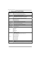
Motherboard Manual 1.3 Motherboard Specifications Specifications Socket 1150 for Intel® Core i7 / i5 / i3 / Pentium / Celeron processor CPU Support Maximum CPU TDP (Thermal Design Power): 95Watt Chipset INTEL® H81 * Please refer to www.biostar.com.tw for CPU support list. Supports Dual Channel DDR3 1066/ 1333/ 1600 Memory 2 x DDR3 DIMM Memory Slot, Max. Supports up to 16 GB Memory Each DIMM supports non-ECC 512MB/ 1/ 2/ 4/ 8 GB DDR3 module * Please refer to www.biostar.com.
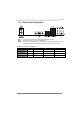
H81MLC 1.4 Rear Panel Connectors Note1: Note2: Note3: VGA port only works with an Intel® integrated Graphics Processor. Maximum resolution: VGA: 1920 x 1200 @60Hz To configure 7.1-channel audio, you have to use a chassis with HD front panel audio module and enable the multi-channel audio feature through O.S. Audio Utility. The 2/ 4/ 5.1/7.1-channel configuration Port 2-channel 4-channel 5.1 channel 7.
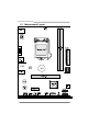
Motherboard Manual 1.5 Motherboard Layout st Note: ■ represents the 1 pin.
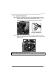
H81MLC CHAPTER 2: HARDWARE INSTALLATION 2.1 Install Central Processing Unit (CPU) Step 1: Locate the CPU socket on the motherboard Note1: Remove Pin Cap before installation, and make good preservation for future use. When the CPU is removed, cover the Pin Cap on the empty socket to ensure pin legs won’t be damaged. Note2: The motherboard might equip with two different types of pin cap. Please refer below instruction to remove the pin cap.
Motherboard Manual Step 4: Hold processor with your thumb and index fingers, oriented as shown. Align the notches with the socket. Lower the processor straight down without tilting or sliding the processor in the socket. Note1: The LGA1155 CPU is not compatible with LGA 1150 socket. Do not install a LGA 1155 CPU on the LGA 1150 socket. Note2: The CPU fits only in one correct orientation. Do not force the CPU into the socket to prevent damaging the CPU.
H81MLC 2.2 Install a Heatsink Step 1: Place the CPU fan assembly on top of the installed CPU and make sure that the four fasteners match the motherboard holes. Orient the assembly and make the fan cable is closest to the CPU fan connector. Ensure the fastener slots are pointing perpendicular to the heatsink. Step 2: Press down two fasteners at one time in a diagonal sequence to secure the CPU fan assembly in place. As each fastener locks into position a click should be heard.
Motherboard Manual 2.3 Connect Cooling Fans These fan headers support cooling-fans built in the computer. The fan cable and connector may be different according to the fan manufacturer. CPU_FAN1: CPU Fan Header Pin 1 2 3 4 Assignment Ground +12V FAN RPM rate sense Smart Fan Control (By Fan) Pin 1 2 3 Assignment Ground +12V FAN RPM rate sense SYS_FAN1: System Fan Header Note: CPU_FAN1, SYS_FAN1 support 4-pin and 3-pin head connectors.
H81MLC 2.4 Install System Memory DDR3 Modules Step 1: Unlock a DIMM slot by pressing the retaining clips outward. Align a DIMM on the slot such that the notch on the DIMM matches the break on the slot. Step 2: Insert the DIMM vertically and firmly into the slot until the retaining clips snap back in place and the DIMM is properly seated. Note: If the DIMM does not go in smoothly, do not force it. Pull it all the way out and try again.
Motherboard Manual Memory Capacity DIMM Socket Location DDR3 Module DDR3_A1 512MB/1GB/2GB/4GB/8GB DDR3_B1 512MB/1GB/2GB/4GB/8GB Total Memory Size Max is 16GB. Dual Channel Memory Installation Please refer to the following requirements to activate Dual Channel function: Install memory module of the same density in pairs, shown in the table. Dual Channel Status DDR3_A1 Disabled O DDR3_B1 X Disabled X O Enabled O O (O means memory installed, X means memory not installed.
H81MLC PEX16_1: PCI-Express Gen2 x16 Slot - PCI-Express 2.0 compliant. Maximum theoretical realized bandwidth of 8GB/s simultaneously per direction, for an aggregate of 16GB/s totally. PEX1_1: PCI-Express Gen2 x1 Slot - PCI-Express 2.0 compliant.
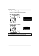
Motherboard Manual 2.6 Jumper Setting The illustration shows how to set up jumpers. When the jumper cap is placed on pins, the jumper is “close”, if not, that means the jumper is “open”. Pin opened Pin closed Pin1-2 closed JCMOS1: Clear CMOS Jumper Placing the jumper on pin2-3, it allows user to restore the BIOS safe setting and the CMOS data. Please carefully follow the procedures to avoid damaging the motherboard. 1 3 Pin 1-2 Close: Normal Operation (default). 1 3 Pin 2-3 Close: Clear CMOS data.
H81MLC 2.7 Headers & Connectors ATXPWR1: ATX Power Source Connector For better compatibility, we recommend to use a standard ATX 24-pin power supply for this connector. Make sure to find the correct orientation before plugging the connector. Pin Assignment Pin Assignment 13 14 15 16 17 18 19 20 21 22 23 24 +3.3V -12V Ground PS_ON Ground Ground Ground NC +5V +5V +5V Ground 1 2 3 4 5 6 7 8 9 10 11 12 +3.3V +3.3V Ground +5V Ground +5V Ground PW_OK Standby Voltage+5V +12V +12V +3.
Motherboard Manual PANEL1: Front Panel Header This 16-pin header includes Power-on, Reset, HDD LED, Power LED, and speaker connection. It allows user to connect the PC case’s front panel switch functions.
H81MLC SATA3~SATA4: Serial ATA 2.0 Connectors These connectors connect to SATA hard disk drives via SATA cables. It satisfies the SATA 2.0 specification and with transfer rate of 3.0Gb/s. Pin 1 2 3 4 5 6 7 Assignment Ground TX+ TXGround RXRX+ Ground F_USB1/2: Header for USB 2.0 Ports at Front Panel This header allows user to add additional USB ports on the PC front panel, and also can be connected with a wide range of external peripherals.
Motherboard Manual F_AUDIO1: Front Panel Audio Header This header allows user to connect the chassis-mount front panel audio I/O which supports HD and AC’97 audio standards.
H81MLC CHAPTER 3: UEFI BIOS & SOFTWARE 3.1 z z 3.2 UEFI BIOS Setup The BIOS Setup program can be used to view and change the BIOS settings for the computer. The BIOS Setup program is accessed by pressing the key after the Power-On Self-Test (POST) memory test begins and before the operating system boot begins. For further information of setting up the UEFI BIOS, please refer to the UEFI BIOS Manual in the Setup DVD.
Motherboard Manual 6. Select the proper BIOS file, and a message asking if you are sure to flash the BIOS file. Click Yes to start updating BIOS. 7. A dialog pops out after BIOS flash is completed, asking you to restart the system. Press the [Y] key to restart system. 8. While the system boots up and the full screen logo shows up, press key to enter BIOS setup.
H81MLC 4. An open dialog will show up to request your agreement to start the BIOS update. Click Yes to start the online update procedure. 5. If there is a new BIOS version, the utility will ask you to download it. Click Yes to proceed. 6. After the download is completed, you will be asked to program (update) the BIOS or not. Click Yes to proceed. 7. After the updating process is finished, you will be asked you to reboot the system. Click OK to reboot. 8.
Motherboard Manual 4. A warning message will show up to request your agreement to start the BIOS update. Click OK to start the update procedure. 5. Choose the location for your BIOS file in the system. Please select the proper BIOS file, and then click on Open. It will take several minutes, please be patient. 6. After the BIOS Update process is finished, click on OK to reboot the system. 7. While the system boots up and the full screen logo shows up, press key to enter BIOS setup.
H81MLC 3.3 Software Installing Software 1. Insert the Setup DVD to the optical drive. The driver installation program would appear if the Auto-run function has been enabled. 2. 3. Select Software Installation, and then click on the respective software title. Follow the on-screen instructions to complete the installation. Launching Software After the installation process is completed, you will see the software icon showing on the desktop. Double-click the icon to launch it.
Motherboard Manual eHot-Line eHot-Line is a convenient utility that helps you to contact with our Tech-Support system. This utility will collect the system information which is useful for analyzing the problem you may have encountered, and then send these information to our tech-support department to help you fix the problem. Note: Before you use this utility, please set Outlook Express as your default e-mail client application program. represents important information that you must provide.
H81MLC Enter the file name and then click “Save”. Your system information will be saved to a .txt file. Open the saved .txt file, you will see your system information including motherboard/BIOS/CPU/video/ device/OS information. This information is also concluded in the sent mail. Note1: We will not share customer’s data with any other third parties, so please feel free to provide your system information while using eHot-Line service.
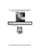
Motherboard Manual CHAPTER 4: USEFUL HELP 4.1 Driver Installation After you installed your operating system, please insert the Fully Setup Driver DVD into your optical drive and install the driver for better system performance. You will see the following window after you insert the DVD The setup guide will auto detect your motherboard and operating system. A. Driver Installation To install the driver, please click on the Driver icon.
H81MLC 4.2 AMI BIOS Beep Code Boot Block Beep Codes Number of Beeps Continuing Description Memory sizing error or Memory module not found POST BIOS Beep Codes Number of Beeps 1 8 4.3 Description Success booting. Display memory error (system video adapter) Troubleshooting Probable 1. 2. There is no power in the system. Power LED does not shine; the fan of the power supply does not work Indicator light on keyboard does not shine. Solution 1. 2. 3. Make sure power cable is securely plugged in.
Motherboard Manual CPU Overheated If the system shutdown automatically after power on system for seconds, that means the CPU protection function has been activated. When the CPU is over heated, the motherboard will shutdown automatically to avoid a damage of the CPU, and the system may not power on again. In this case, please double check: 1. The CPU cooler surface is placed evenly with the CPU surface. 2. CPU fan is rotated normally. 3. CPU fan speed is fulfilling with the CPU speed.
H81MLC APPENDIX: Specifications in Other Languages Arabic اﻟﻤﻮاﺻﻔﺎت ﻗﺎﻋﺪة وﺣﺪة اﻟﻤﻌﺎﻟﺠﺔ اﻟﻤﺮآﺰﻳﺔ ﻣﺠﻤﻮﻋﺔ اﻟﺸﺮاﺋﺢ اﻟﻤﺄﺧﺬ 1150ﻟﻤﻌﺎﻟﺞ اﻳﻪ إم دى Intel® Core i7 / i5 / i3 / Pentium / Celeron اﻟﺤﺪ اﻷﻗﺼﻰ ﻟﻠﻄﺎﻗﺔ اﻟﺤﺮارﻳﺔ ﻓﻲ ﺗﺼﻤﻴﻢ اﻟﻤﻌﺎﻟﺞ ) 95 :( thermal design power – TDPواط. * ﻳﺮﺟﻰ اﻟﺮﺟﻮع إﻟﻰ اﻟﻤﻮﻗﻊ www.biostar.com.twﻟﻘﺎﺋﻤﺔ دﻋﻢ اﻟﻤﻌﺎﻟﺞ .CPU IINTEL® H81 DDR3 1066/ 1333/ 1600ﺗﺪﻋﻢ ﻗﻨﺎة ﻣﺰدوﺟﺔ دي .دي .ار. اﻟﺬاآﺮة 2xدي .دي .ار DDR3 .
Motherboard Manual French Spécifications Socket 1150 Processeurs Intel® Core i7 / i5 / i3 / Pentium / Celeron Support Unité Enveloppe thermique Unité Centrale maximum : 95Watt Centrale * Veuillez vous reporter à www.biostar.com.tw pour la liste des supports modèles d'Unité Jeu de puces INTEL® H81 Centrale. Supporte mémoire DDR3 double canal 1066/ 1333/ 1600 Mémoire Banc de mémoire 2 x DDR3 DIMM, Supporte max.
H81MLC German Spezifikationen Anschluss-1150 für Intel® Core i7 / i5 / i3 / Pentium / Celeron Prozessor CPU-Unterstützung Maximale CPU TDP (Thermal Design Power): 95 Watt Chipset INTEL® H81 * Bitte konsultieren Sie www.biostar.com.tw für CPU-Unterstützungsliste Unterstützt zweikanaliges DDR3 1066/ 1333/ 1600 Festplattenspeicher 2 x DDR3 DIMM-SpeicherSlot, Max. Uterstützung bis zu 16 GB-Speicher Jedes DIMM unterstützt nicht-ECC 512MB/ 1/ 2/ 4/ 8 GB DDR3-Module * Bitte konsultieren Sie www.biostar.com.
Motherboard Manual Italian Specificazioni Supporto processore Tipo scheda Slot 1150 per processore Intel® Core i7 / i5 / i3 / Pentium / Celeron Alimentazione di Proiezione Termico (TDP – Thermal Design Power): 95Watt * Si prega di consultare www.biostar.com.tw per la lista di supporto del processore.
H81MLC Japanese 仕様 Intel® Core i7 / i5 / i3 / Pentium / Celeron プロセッサの Socket 1150 CPU サポート 最大 CPU TDP (Thermal Design Power 最大放熱量):95 W *CPU サポート リストについては、www.biostar.com.twを参照してください。 チップセット INTEL® H81 デュアルチャンネル1066/ 1333/ 1600 をサポート 2 x DDR3 DIMM メモリ スロット、 最大 16 GB メモリまでサポート メモリ 各 DIMM は、非-ECC 512MB/ 1/ 2/ 4/ 8 GB DDR3 モジュールをサポートしています *サポートされているメモリのリストについては、www.biostar.com.
Motherboard Manual Polish Specyfikacje techniczne Gniazdo procesora (Socket) 1150 dla procesorów Intel® Core i7 / i5 / i3 / Pentium / Celeron Obsługa procesora Moc Wydzielanego Ciepła (TDP - Thermal Design Power): 95Watt * Proszę sprawdzić listę obsługiwanych procesorów na stronie internetowej www.biostar.com.
H81MLC Portuguese Especificações Porta 1150 para processador Intel® Core i7 / i5 / i3 / Pentium / Celeron Suporte Processador Alimentação de Design Térmico (TDP – Thermal Design Power): 95Watt * Por favor consulte www.biostar.com.tw para obter uma lista de suporte do processador. Tipo Placa Mãe INTEL® H81 Suporta DDR3 1066/ 1333/ 1600 Canal Duplo Memória 2 x DDR3 DIMM Slot de memória Suporta até 16 GB Memória Cada DIMM suporta non-ECC 512MB/ 1/ 2/ 4/ 8 GB DDR3 módulo * Por favor consulte www.biostar.
Motherboard Manual Russian Спецификации Поддержка Сокет 1150 для процессоров Intel® Core i7 / i5 / i3 / Pentium / Celeron центрального Максимальный термопакет центрального процессора (TDP): 95 ватт процессора * Перечень поддержки центрального процессора смотрите на www.biostar.com.tw.
H81MLC Spanish Especificaciones Compatibilidad con el procesador Tipo de Placa Memoria Almacenamiento de información LAN Códec Audio USB Ranuras de Extinción Panel trasero de E/S Conectores en placa Factor de Forma Soporte OS Ranura 1150 para procesador Intel® Core i7 / i5 / i3 / Pentium / Celeron Alimentación de Proyección Térmica (TDP – Thermal Design Power): 95Watt *Por favor consultar con www.biostar.com.tw para la lista de compatibilidad con el procesador.