
Manual


Problem Possible Cause Solution
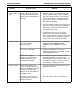
Conductivity trace
does not follow
exactly the
theoretical gradient
trace %B.
Distorted Mixer capacity is
conductivity trace. incorrect
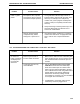
12.5 TROUBLESHOOTING THE MAXIMIZER BUFFER BLENDING
Problem Possible Cause Solution
No values for pH There may be a loose or
are displayed on incorrect cable connection.
the Controller
status bar.
Noisy or unstable Air bubble on pH probe
readings membrane
Drift Solution temperature is
changing
Fluctuations Changes in salt concentrations
observed in pH during a run may cause errors
readings during run in the observed pH
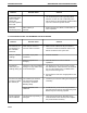
The observed buffer The software pH correction
pH does not match may have been entered
the desired pH. incorrectly in the Buffer
Blending Setup.
The pH electrode is not
calibrated.
The pH elecrode The electrode may be dirty or
will not calibrate damaged.
TROUBLESHOOTING MAINTENANCE AND TROUBLESHOOTING
12-10
1. The Conductivity flow cell is typically placed
after the UV flow cell. The Conductivity trace
will be offset from the theoretical gradient based
upon the column and system volume.
1. Refer to Section 2.4, Mixers, for discussion of
mixer capacities.
1. Make sure the cable from the pH monitor is
connected to a SIM or Maximizer and that the
SIM is connected to the system bus.
1. Remove air bubble.
1. Allow all solutions to come to thermal
equilibrium.
1. The actual pH is may not be in error but only
the observed pH. Collect fractions and measure
the pH of the solution using a suitable bench
top pH monitor during a run.
2. Ensure that the mixer size is appropriate for the
flow rate.
1. Check the pH correction setting and change it if
necessary.
2. Recalibrate the pH electrode using standards
that span the pH range of the buffer being used.
Buffers may be incorrectly prepared.
1. Clean the pH electrode as described in the
instructions that came with the probe. Replace
the pH electrode if necessary.