
Manual
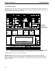
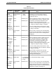
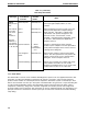


Table 7-1.
Valve Setup Information
MODES OF OPERATIONSYSTEM OPERATION
7-7
Notes
Functions as a fraction collection diverter,
determined by the actual fraction collection
parameters chosen.
When used before the inlet to Pump A or B, the
valve enables buffer selection. The buffer name
specified for each position will appear in the
Protocol screen’s “Isocratic Flow”, “Linear
Gradient”, and “Change Valve” dialog box. Refer
to Chapter 8, Sample Loading, for examples.
Used for auxiliary pump load selection to select
one of two solutions. Refer to Chapter 8, Sample
Loading, for examples.
When used for a purpose other than described
above. The name specified for each position will
appear in the Protocol screen’s “Change Valve”
dialog box.
When used before the inlet to Pump A or B, the
valve provides preparative sample loading or
buffer selection. The buffer or sample name
specified for each position will appear in the
Protocol screen’s “Isocratic Flow”, “Linear
Gradient”, and “Change Valve” dialog box. Refer
to Chapter 8, Sample Loading, for examples.
Used for auxiliary pump load selection to select
one of four solutions. Refer to Chapter 8, Sample
Loading, for examples.
When used for a purpose other than that
described above. The name specified for each
position will appear in the Protocol screen’s
“Change Valve” dialog box.
For automatically loading a sample.
When used for a purpose other than described
above. The name specified for each position will
appear in the Protocol screen’s “Change Valve”
dialog box. Refer to Section 4, Advanced System
Applications, Chapters 8 through 10.
Valve Type Valve Name/ Position
Function Names
SVT3-2 Fraction Collector 1 Waste
Low pressure Diverter 2 Collect
solenoid valve
Note: Indicate Inlet A Named by user
the location
of the valve Inlet B Named by user
cable
connection.
When the
Maximizer is Aux Pump Inlet Named by user
used, inlets A
and B become
A1, A2, B1, B2.
User Assigned Named by user
Name
SV5-4 Inlet A Named by user
Low pressure
solenoid valve Inlet B Named by user
Note: Indicate
the location
of the valve
cable
connection. Aux Pump Inlet Named by user
When the
Maximizer is
used, inlets A User Assigned Named by user
and B become Name
A1, A2, B1, B2.
AVR7-3 Sample Inject 1 Load Sample
High pressure 2 Inject Sample
valve 3 Purge
Note: Indicate User Assigned Named by user
the location Name
of the valve
cable
connection