
Instruction Manual


List of Figures
Page
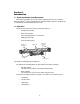
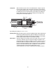
Figure 1 DynaLoop 25 and DynaLoop 90 Sample Loops ..........................1
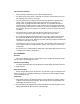
Figure 2 Sliding Seal Assembly (Load Phase) ...........................................2
Figure 3 Sliding Seal Assembly (Flush Phase) ..........................................3
Figure 4 DynaLoop Plumbing Connections...............................................5
Figure 5 Injection Valve Plumbing Connections........................................5
Figure 6 Injection Valve Positions ..............................................................6
Figure 7 Rear Panel of BioLogic Workstation with AUX Connector .........7
Figure 8 Peristaltic Pump Tubing Connections .........................................8
Figure 9 DynaLoop Cleaning ....................................................................12
Figure 10 Removing the Filter.....................................................................13
Tables
Table 1 Troubleshooting the DynaLoop..................................................11
Table 2 DynaLoop Replacement Parts....................................................15