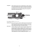
0 5 10 15 20 25 30 0 5 10 15 65 60 55 50 45 40 35 20 70 75 80 85 90 25 DynaLoop™ 25 and DynaLoop 90 Instruction Manual Catalog Numbers 750-0451 (25 ml) 750-0452 (90 ml) For technical support, call your local Bio-Rad office, or in the U.S.
Table of Contents Page Section 1 Introduction.....................................................................................1 1.1 1.2 DynaLoop Sample Loop Description............................................................1 Operation ....................................................................................................1 Section 2 Installation.......................................................................................3 2.1 2.2 2.3 Unpacking .........................
List of Figures Page Figure 1 DynaLoop 25 and DynaLoop 90 Sample Loops ..........................1 Figure 2 Sliding Seal Assembly (Load Phase) ...........................................2 Figure 3 Sliding Seal Assembly (Flush Phase) ..........................................3 Figure 4 DynaLoop Plumbing Connections ...............................................5 Figure 5 Injection Valve Plumbing Connections........................................5 Figure 6 Injection Valve Positions ............
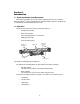
Section 1 Introduction 1.1 DynaLoop Sample Loop Description The DynaLoop sample loop is a large-volume sample injection loop for use with the BioLogic DuoFlow™ system. Available in 25 ml and 90 ml sample capacities, the DynaLoop is used with the automated AVR7-3 injection valve. 1.
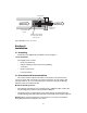
Load phase With the AVR7-3 injection valve in the LOAD position, sample is injected into the sample chamber end of the DynaLoop via port 3 on the injection valve using a peristaltic pump or a syringe. As the DynaLoop fills with sample, the sliding seal moves toward the buffer end assembly. The sliding seal O-ring and closed check valve within the sliding seal assembly prevent mixing of buffer and sample (Figure 2).
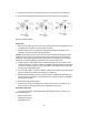
O-ring seals SAMPLE BUFFER Sample end connector Check valve (open) Sliding seal assembly in contact with sample end connector Fig. 3. Flush phase. (Check valve is open.) Section 2 Installation 2.1 Unpacking The DynaLoop is shipped fully assembled as shown in Figure 1. List of components The shipping carton contains: • DynaLoop sample loop • Fittings and tubing to make all necessary plumbing connections • DynaLoop spare parts • Instruction manual 2.
Important Considerations • Always follow good laboratory practices when handling solvents. • Use buffers and solvents that are chemically clean and free of particulates; purify and filter all buffers and solvents as necessary. • The wetted materials of the DynaLoop are Tefzel, glass-filled Ryton (polyphenylene sulfide), PTFE, and PEEK (polyether-ether ketone).
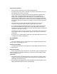
Make Connections 1. To make a collet/nut connection at the end of the DynaLoop, slide a collet/nut fitting and ferrule over the end of the cut tubing. Make sure the tapered end of the ferrule faces the tubing end. The blunt end of the ferrule must face the collet/nut (Figure 4). 2. Push the tubing all the way into the connector until the tube bottoms in the fitting. 3. While pressing the tubing securely into the fitting, slide the ferrule and collet/nut toward the DynaLoop and finger-tighten the collet/nut.
3. Connect the sample end of the DynaLoop to port 3 of the injection valve (Figure 6). 4. Connect the buffer end of the DynaLoop to port 6 of the injection valve (Figure 6). Fig. 6. Injection valve positions. Purge Lines 1. Disconnect the tubing from the column at the column inlet (port 4) and redirect port 4 to a suitable waste container using a short piece of tubing. 2. Switch the injection valve to INJECT. Set the BioLogic DuoFlow pump flow rate to 10 ml/min. Verify that the DynaLoop fills with buffer.
Electrical Connections (Model EP-1 Econo Pump) 1. Turn off the BioLogic DuoFlow controller and workstation. 4 COND CHART UV OPTICS TEST PORT COND FLOWCELL UV LAMP AUTOMATED VALVES UV CHART INSTR BUS 5 6 SOLONOID VALVES 2. Connect the EP-1 Econo pump to the BioLogic DuoFlow workstation using System Cable 7 (mini-DIN to breakout, catalog number 731-8267). Plug the mini-DIN end of System Cable 7 into the Econo pump rear connector labeled AUX.
6. Some air may still be trapped in the sample chamber of the DynaLoop. If so, switch the injection valve to the INJECT position and again empty the sample chamber of the DynaLoop to the column inlet waste container. 7. Continue to purge all the air from the system by switching between LOAD and INJECT as described in steps 5 and 6. Terminate this purging procedure with the valve in the LOAD position and with the sliding seal assembly in contact with sample end fitting.
2. Connect the Econo gradient pump inlet tube to a reservoir of buffer. Switch the injection valve to the INJECT position. Set the BioLogic DuoFlow flow rate to 10 ml/min. Verify that the DynaLoop fills with buffer. Caution: The sliding seal must move toward the sample end of the DynaLoop. If the seal moves toward the buffer end of the DynaLoop (the end with the white filter), stop the pump immediately. The DynaLoop was installed backwards. Correct the plumbing configuration before using the DynaLoop. 3.
Load Sample Manually (via a syringe) 1. With the injection valve in the INJECT position, allow the sliding seal to contact the sample end fitting. Set the valve to the LOAD position. Load sample into the DynaLoop by using a syringe at the filler port (port 2). Hint: use a 1/4-28 – Female Luer adaptor at port 2 (part no. 910-4159). As sample is loaded into the loop it displaces the buffer that was used to purge the unit. 2.
d. In the Inject Sample area of the window, select the Injection Buffers, the buffer composition, the flow rate of the BioLogic DuoFlow workstation pumps, and the sample volume to be injected onto the column. The BioLogic DuoFlow system will now automatically control the loading and injection of the sample. Note that the rinse function is not available when the DynaLoop is being used. 4. Continue writing your desired separation protocol.
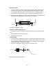
4.2 Cleaning and Storage Refer to Figure 9 as you follow these instructions. Guide, check valve Spring, PTFE coated Ball, rubber O-ring, coated Cap Housing End cap, buffer cap, sample 0 O-ring Sliding seal assembly 5 10 15 20 25 Glass tube assembly, 25 ml Glass tube assembly, 90 ml Shield, 25 ml Filter Shield, 90 ml O-ring Fig. 9. DynaLoop cleaning. Cleaning and Storage With the DynaLoop in the fluid path, use the BioLogic DuoFlow pump to deliver the cleaning solutions to the DynaLoop. 1.
Reassembly 1. Hold the body of the sliding seal assembly in one hand. Insert, in order, the rubber ball, the check valve guide, and spring into the hole in the center of the sliding seal housing. Place the O-ring in the groove at the top of the housing. Screw the retainer cap onto the body. (Ensure that the spring enters the large hole in the center of the cap.) 2. Insert the sliding seal assembly into the glass tube.
Caution: Do not pry against the black plastic lip on the end fitting that holds the O-ring. The connector tip may break, causing the DynaLoop to leak. Installing New Filter 1. Check that the new filter contains a distributor and snap the replacement filter onto the black connector tip. 2. Insert the buffer end cap into the glass column and thread the end cap into the plastic jacket by turning clockwise. 4.
Section 5 Appendix A Replacement Parts Table 2. DynaLoop Replacement Parts Product Description DynaLoop Parts Kit, includes end cap O-rings, sliding seal O-ring, filter, collet/nut fittings, 1/8” ferrules, 1/4-28 nuts and ferrules, and 1/8” PTFE tubing.
Bio-Rad Laboratories, Inc. Web site www.bio-rad.