
User Manual

3
I. BioLogic DuoFlow System
Section 1. DuoFlow System Preparation
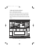
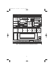
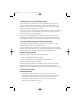
When the DuoFlow system is turned on, the Manual screen is displayed (see
Figures 1 and 2). This screen displays instrument control panels that provide
direct control of the pumps, valves, fraction collector, UV detector, QuadTec
™
UV/Vis detector, and Econo
™
Gradient Pump. The arrow button in the upper
right corner of the detector control panel toggles between the UV and QuadTec
detector control panels. Only those instruments connected to the system will be
displayed.
BioLogic Duo-Flow - - - no method -
Edit
Method
New
Method
New
Run Browser Manual Setup Setup
Protocol
wash
load
1
2
Run
Notes
Report
PostRun
Log
Advance
Fraction Collector: BioFrac
START
Gradient Pump: F10
Inlet A
1.00
50
50
Inlet B
Flowrate
ml/min
%
%
High
limit
0
700
Low
limit
psi.
AVR7-3 at port 4
Workstation Valves
SVT5-4 at port 1 SVT3-2 at port 3SV5-4 at port 2
P
L21
2
1
3
4
2
1
3
4
STOP
START STOP
START STOP
Set
Event Mark
OFFON
psi.
Econo Gradient Pump 1
EGP %B
1.000
0
0.00
% Split
Flow
Direction
Flowrate
ml/min
%
%
Set
Tube number:
ml
Volume left:
Mode: System
Local
Conductivity range
(mS/cm):
Mode: System
Local
Start Tube:
End Tube:
Fraction size:
1
1
20
1.00
5
1.0
I
AVR9-8 at port 5
37
82
6
5
4
I
AVR9-8 at port 6
37
82
6
5
4
I
UV Detector
Chart Recorder
ON OFF
Zero Baseline
100% Buffer B
02 4 6 8
10
Minutes
AU
mS/cm
1.50
1.00
0.50
50
0.00
0.0
400.0
300.0
200.0
100.0
Fractions
UV Conductivity
Clear
Traces
Resize
UV range (AU):
Flow Rate EGP %B
0 %B0.00 ml/min 0%
% Split
0.00 ml/min
50 %B
Gradient Pump: F10 UV Conductivity
1 psi 0.2583 AU 0.000 mS/cm
QuadTec
Econo Gradient
Pump
SIM1/pHSIM1/SIG
Settings
File View Utilities Options Window Help
Bio-Rad
Web
Rack:
F1 (12-13 mm tubes)
Zero baseline for the UV detector
Fig. 1. Manual Control Screen with UV detector
4006208B.qxd 6/28/2004 11:03 AM Page 8