
Instruction manual


6
Description of Components
2.0 DESCRIPTION OF COMPONENTS
The following sections identify the key features of each of the major system components.
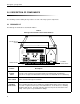
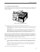
2.1 BIOLOGIC LP
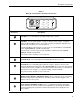
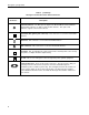
The BioLogic LP Controller is described in Table 2.
Table 2.
BioLogic LP Controller’s Front Panel Features
Feature Description
Control Consists of the control keys and status LEDs for monitoring and controlling the
Panel system. It is designed to withstand the minor spills associated with use in a laboratory.
Power switch Turns on/off the BioLogic LP Controller.
Plumbing The peristaltic pump may be used with most flexible tubing having an inner diameter
Connections less than or equal to 3.2 mm (1/8”) and a wall thickness of 1.0 mm or less, including
PharMed, and silicone. Inlet and outlet lines attach to the ports at the bottom of the
pump. These ports accept standard luer fittings.
POWER ON/OFF
PLUMBING
CONNECTIONS
PLATEN ADJUST
SCREW
MODE
INSTR
Alarm
Fraction Collector
Chart Recorder
Pump
UV Lamp
Cond
Mark
?
Help
Pump
Manual
Collector
Program
Alarm
Run
UV
Previous Next
Valves Recorder
4
12
5
7
C
0
8
3
6
.
9
BioLogic LP