BIOLOGIC LP CHROMATOGRAPHY SYSTEM INSTRUCTION MANUAL Catalog Numbers 731-8300 731-8301
Table of Contents TABLE OF CONTENTS Safety Getting Started Quickly Chapter 1.0 1.1 1.2 1.3 1.4 Introduction...................................................................................................................1 Overview.........................................................................................................................1 Features .........................................................................................................................2 Unpacking.............
Table of Contents 5.3.5.3 Collection Windows Mode ....................................................................67 5.3.5.4 Threshold and Collection Windows Mode............................................70 5.3.6 Programming Mode’s Alarm Table ......................................................................62 5.3.7 Entering Method Names .....................................................................................75 5.4 Run Mode............................................................
Table of Contents 22. 23. 24. 25. 26. 27. 28 29. 30. 31. 32. List of Methods ...............................................................................................................................52 Programming a New Method..........................................................................................................55 Programming: The Pump Table......................................................................................................
Safety SAFETY ! Caution/Warning Disconnect power to any BioLogic LP component before servicing. No userserviceable parts are inside any component. Refer servicing to Bio-Rad service personnel. The Bio-Rad BioLogic LP is certified to meet the I.E. C. 1010* safety standard for safety of laboratory equipment. Certified products are safe to use when operated in accordance with the instruction manual. This safety certification does not extend to other chromatography equipment or accessories not I.E.C.
Getting Started GETTING STARTED QUICKLY This manual provides detailed discussion of the use and maintenance of the BioLogic LP system. Listed below is an overview of the steps involved in setting up and using your system. Setting up the electrical and plumbing connections: 1. Connect system cabling, as shown in Figure 11, System Cable Connections. Note the following: a. Chart recorder: Be sure to plug the conductivity signal banana plugs into Channel 2 of the chart recorder.
Getting Started 3. Make final adjustments. From the Mode keys select Manual, and from the Instrument keys select Pump. Start the pump, and with fluid flowing through the system, check the following: a. Check the range setting for the UV Monitor, zero the UV Monitor, and position the Channel 1 pen on the chart recorder. b. Check the range setting for the Conductivity Monitor, and position the Channel 2 pen on the chart recorder. c. Check that a sufficient number of tubes are in the fraction collector rack.
Introduction 1.0 INTRODUCTION 1.1 OVERVIEW The BioLogic LP low-pressure, gradient chromatography system is designed for the purification of proteins, peptides, and other biomolecules where recovery of biological activity is of primary concern. The BioLogic LP Controller is microprocessor controlled, with easy-to-use front panel controls and menu-driven software for manual operation, system setup, method editing and run operations.
Introduction 1.2 FEATURES The BioLogic LP System provides the following features: 2 • A space-saving modular and stackable design which minimizes the system footprint on the bench. • Programming separation methods is menu-driven, easy and intuitive using either Time-based or Volume-based steps. Method storage capacity easily meets most laboratory requirements. • On-screen help function.
Introduction 1.3 UNPACKING When you receive the BioLogic LP System, carefully inspect the shipping containers for any damage which may have occurred in shipping. Severe damage to a container may indicate damage to its contents. If you suspect damage to the contents may have occurred, immediately file a claim with the carrier in accordance with their instructions before contacting Bio-Rad Laboratories.
Introduction Table 1. (continued) Description of System Components Component Function System Rack This is the system organizer for columns and cartridges, buffer containers, sample inject and buffer select valves, UV and Conductivity Flow Cells, and other devices used with the system. The optional BioLogic Rack Expansion kit is available to extend the rack to 3 trays. Proportioning Valve/Mixer Module This combination of valve and mixer module mixes and proportions two buffers.
Introduction Table 1. (continued) Description of System Components Component Chart recorder Function Bio-Rad offers the Model 1327 Chart Recorder as a system option. This is a dual pen chart recorder for Conductivity and UV Detector readings. Stop/Start and Pen Up/Down functions are controlled by the BioLogic LP Controller. Chart speed is set at the recorder itself (the BioLogic LP Controller does not control this function).
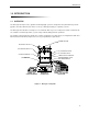
Description of Components 2.0 DESCRIPTION OF COMPONENTS The following sections identify the key features of each of the major system components. 2.1 BIOLOGIC LP The BioLogic LP Controller is described in Table 2. Table 2. BioLogic LP Controller’s Front Panel Features PLATEN ADJUST SCREW BioLogic LP Pump Fraction Collector UV Lamp Chart Recorder Alarm Mark ? 1 2 3 4 5 6 7 8 9 C 0 .
Description of Components Table 3. BioLogic LP Controller’s Rear Panel Connectors UV LAMP Connector UV OPTICS BUFFER SELECTOR FRACTION COLLECTOR UV CHART BYPASS VALVE INSTR. BUS COND FLOWCELL DIVERTER VALVE COND CHART GRADIENT MIXER AUX 12 V Description UV Optics: For connecting the UV Optics module to the system. UV Chart: For UV signal output to a single or dual pen chart recorder.
Description of Components Table 3. (continued) BioLogic LP Controller’s Rear Panel Connectors Connector Description Fraction Collector: The BioLogic LP supports the Bio-Rad Model 2110 and Model 2128 fraction collectors, as well as other fraction collectors. This port sends “Advance” signals to the fraction collector. Instrument bus (phone jack connector): This connector is reserved for internal BioRad use. Test Port: This connector is reserved for internal Bio-Rad use.
Description of Components 2.2 PROPORTIONING VALVE/MIXER MODULE This is a combination proportioning valve and mixer. The solenoid valve proportions the two solutions for the purpose of forming linear gradients, and the dynamic mixer rapidly mixes them. It can be mounted to the system rack or left free-standing. M IX B ER A Figure 2.
Description of Components 2.3 UV DETECTOR The UV Detector, which consists of the UV Optics Module and the control circuitry within the BioLogic LP Controller, is a single beam, fixed wavelength UV absorbance detector specifically designed for protein chromatography. The UV Optics Module can be positioned close to a column outlet, minimizing system dead volume and remixing of peaks. When connecting the UV Optics Module to the system, note the flow direction arrows on the top of the UV Optics Module’s case.
Description of Components Figure 3 shows how the flow cell and the filters can be changed. To remove the flow cell, you will need to remove the retaining clip from the bottom of the optics module and pull the luer connectors away from their holders. Then loosen the thumbscrews and remove the flow cell. When inserting the replacement flow cell, make sure the O-ring is securely placed on the flow cell. To change the filter, loosen the filter’s thumbscrew and lift out and rotate the filter holder.
Description of Components 2.5 BIO-RAD SYSTEM OPTIONS Bio-Rad offers a number of system options for use with your BioLogic LP. The following instrument options are described in this section. • Models 2110 and 2128 Fraction Collector • Model 1327 Chart Recorder 2.5.1 Model 2110 Fraction Collector The Model 2110 collects up to 80 fractions in a motor-driven carousel. It uses standard 13 x 100 test tubes. An optional adapter is available for use with 1.5 ml microcentrifuge test tubes.
Description of Components 2.5.2 Model 2128 Fraction Collector The Model 2128 provides X/Y motion drop-dispensing, accommodating a wide range of tube diameters and lengths, microtiter plates, microtubes, and “bottle size” fractions. It is ideally suited for both analytical and preparative applications. MOD E FRA L 2128 CTIO N CO LLE CTO R Thre sh Next old tu Drain be 2 ADV ing COL L STO P 7 4 1 8 5 2 HELP 9 6 3 CE 0 . Figure 6.
Description of Components 2.5.3 Model 1327 Chart Recorder When used with the BioLogic LP, the Model 1327 Chart Recorder automatically starts when a method begins and stops when the method ends. The BioLogic LP’s Manual mode operation of the chart recorder may be used to start and stop the chart recorder.
Description of Components 2.6 NON-BIO-RAD SYSTEM OPTIONS Non-Bio-Rad fraction collectors and chart recorders may be used with the BioLogic LP, as discussed in the following sections. UV LAMP UV OPTICS BUFFER SELECTOR FRACTION COLLECTOR UV CHART BYPASS VALVE INSTR. BUS COND FLOWCELL DIVERTER VALVE COND CHART GRADIENT MIXER 8 7 5 4 2 6 3 1 AUX 12 V Figure 8. Pin Assignments for BioLogic LP’s Fraction Collector and Chart Recorder Connectors 2.6.
Description of Components If you are using a non-Bio-Rad fraction collector, use an SV-3 diverter valve to enable advanced features such as collection by Threshold and/or Collection Windows. If this optional valve is not used, then only Collect All is available. 2.6.2 Non-Bio-Rad Chart Recorders A non-Bio-Rad chart recorder may be used with the BioLogic LP. A mini-DIN to banana plug cable (System Cable 4) is used to connect the BioLogic LP Controller’s UV Chart port to the chart recorder.
System Connections 3.0 SYSTEM CONNECTIONS When setting up the system, consider the amount of bench space available, the instruments to be used with the system, and the devices to be used with the System Rack. The BioLogic LP can be set up wherever there is available bench space and sufficient power outlets, including in 4° cold rooms or cold boxes. When used in a cold environment, it is recommended that you leave system power “ON” to minimize condensation.
System Connections To set up the BioLogic LP System: 1. BioLogic LP Controller. a. Place the BioLogic LP Controller on the bench and turn the unit so that the back side faces you. b. Connect the power cable. Do not turn on the unit. 2. System Rack. Assemble the Rack and place it on the BioLogic LP Controller, as described below. a. Fit the tapered collars into the ringed grooves on the rods.
System Connections c. Insert the two short rods into the remaining holes. d. Mount the 2-piece column clamping arrangement across the two long rods using the attached thumbscrews. e. The horizontal bar may be positioned between the upright bars using the rod clamps (tightened by the Allen wrench) supplied with the system. f. Place the rack into the four corner holes of the BioLogic LP Controller.
System Connections MODEL 1327 CHART RECORDER SYSTEM CABLE 2 UV OPTICS MODULE SV-5 BUFFER SELECT VALVE SYSTEM CABLE 4 SYSTEM CABLE 15 CONTROLLER SYSTEM CABLE 1 SV-3 COLUMN BYPASS SV-3 DIVERTER VALVE (2110 FRACTION COLLECTOR) CONDUCTIVITY FLOW CELL MODEL 2128 FRACTION COLLECTOR MIXER B A OR PROPORTIONING VALVE AND MIXER MODULE SYSTEM CABLE 3 Figure 11.
System Connections 6. Chart Recorder; Model 1327. The Model 1327 chart recorder may be positioned on the rack shelf or on the bench. a. Connect System Cable 2 between the BioLogic LP Controller and the recorder as follows: • The mini-DIN connector is connected to the port marked “UV Chart” on the rear of the BioLogic LP Controller. • The DIN connector is connected to the single DIN port on the side of the chart recorder.
System Plumbing 4.0 SYSTEM PLUMBING This chapter begins with discussion of plumbing practices and general guidelines, followed by a general procedure for plumbing the major system components. Later sections discuss how to plumb Bio-Rad’s low pressure valves. 4.1 GENERAL GUIDELINES FOR PLUMBING THE SYSTEM The BioLogic LP uses the following tubing: • System tubing: 0.8mm ID or 1.6mm ID Tygon tubing. • Pump Tubing: 0.8mm ID, 1.6mm ID, or 3.2mm ID PharMed tubing.
System Plumbing All plumbing connections require Luer fittings. A fittings kit is included with the BioLogic LP system. The figure below shows the different Luer connectors available for use in plumbing the BioLogic LP system. MALE LUER FOR SYSTEM TUBING CONNECTIONS FEMALE LUER FOR PUMP TUBING MALE-TO-MALE CONNECTOR FEMALE 'T' CONNECTOR Figure 12. Luer Fittings When plumbing the system, be sure to keep tubing lengths to a minimum. Also, all fittings should be fingertight.
System Plumbing 4.2 ADJUSTING THE PLATEN AND PLUMBING THE PERISTALTIC PUMP The peristaltic pump requires the following tubing lengths: • PharMed 179 ±1.5mm • Silicone 171±1.5mm Note: PharMed is preferred. (Tygon should not be used in the pump head because it fatigues rapidly.) If you are not using pre-cut tubing, cut the tubing to the lengths indicated above. 1. Proper adjustment of platen pressure increases flow stability, minimizes flow pulsation, and prolongs the life of the tubing.
System Plumbing 2. Pull the platen cam lever away from the pump head to unlock the platen and slide the platen away from the pump head frame assembly, exposing the rollers. 3. Slip a lock-ring onto one end of the tubing. The lock rings must be put on before luer fittings, and the recessed parts of the lock rings should face each other. The size and color of each lock ring is as follows: Tubing ID 0.8 mm (1/32”) 1.6 mm (1/16”) 3.
System Plumbing 4.3 PLUMBING THE SYSTEM 1. Plumbing the inlets to the Proportioning valve/Mixer module. a. Cut two suitable lengths of Tygon tubing (0.8mm ID or 1.6mm ID). b. Attach the barbed end of a male luer to one end of each piece of tubing. (Warming the Tygon tubing in warm water makes it more flexible and easier to work with.) c. Connect each fitting to one inlet port of the Proportioning valve. Twist the fitting clockwise to lock. Do not over-tighten. d.
System Plumbing SAMPLE LOOP INJECT PORT MV-6 INJECT VALVE WASTE FILL CONTROLLER SV-3 COLUMN BYPASS VALVE COMMON SV-5 BUFFER SELECT WASTE SV-3 COLUMN C E UV OPTICS MODULE D CONDUCTIVITY FLOW CELL COMMON PROPORTIONING VALVE AND MIXER MODULE WASTE SV-3 DIVERTER VALVE SV-3 MIXER B B A BUFFERS B AND A A COLLECT TO MODEL 2128 FRACTION COLLECTOR OR COLLECT TO MODEL 2110 FRACTION COLLECTOR Figure 14.
System Plumbing 6. Plumbing the MV-6 Valve’s Sample Loop. Plumb the inject valve’s sample loop according to Figure 14. Use male luer fittings at each end of the loop tubing. A sample loop of any volume can be prepared. Volumes may be determined empirically, or by following the example below: Total volume of sample = Valve volume + Fittings volume + Tubing volume where, Volume valve passage and fittings = .325 ml Tubing volume = Length of tubing x Volume/cm, as determined from the following: ID Volume/cm 0.
System Plumbing 9. Plumbing the UV Optics Module and Conductivity Flow Cells. a. Connect the column outlet line to the inlet port of the UV Optics Module. (Arrows on the UV Optics Module indicate flow direction.) b. Cut a short length of Tygon tubing and attach luer fittings to each end. Screw one end into the output port of the UV Optics Module’s flow-cell and the other end into the Conductivity Flow Cell. (Note: The Conductivity Flow Cell is bi-directional.) c.
System Plumbing c. Using an SV-3 Diverter valve: Mount the valve on the System Rack so that it is as close as possible to the Model 2128 Fraction Collector. Plumb the system as shown in Figure 14. (Note: This configuration requires the valve be connected to the Diverter Valve port on the BioLogic LP.) When you turn on the Model 2128, select “Econo” mode from the Model 2128’s startup screen. The system prompts with the message “Is 2128 valve cable connected.” (This refers to System Cable 3.) Answer NO.
System Operation 5.0 SYSTEM OPERATION 5.1 FRONT PANEL CONTROLS Table 5. Front Panel Controls BioLogic LP Pump Fraction Collector UV Lamp Chart Recorder Alarm Mark ? 1 2 3 4 5 6 7 8 9 C 0 . Help Previous Next MODE Manual Program Run Pump Collector Alarm INSTR UV Key Cond Valves Recorder Description Softkeys: These four keys are located directly below the LCD display.
System Operation Table 5. (continued) Front Panel Controls Key Description Mark key: This key signals the chart recorder to put an event mark on the UV trace. Mark Help key: Pressing this key at any time displays information about the screen that is currently displayed. Use the Prev and Next keys to scroll through the Help screens. To exit help, again press the Help key.
System Operation Table 5. (continued) Front Panel Controls Key Description Instr Instr (Instrument) keys: These keys allow you to select individual instruments to control. The selected component is indicated by its corresponding LED on the front panel and its corresponding control screen is displayed. Note that the Pump, Collector, and Alarm keys are grouped in a shaded area, indicating that these functions (pump operation, fraction collection, and alarms) are programmed as part of a separation method.
System Operation 5.2 MANUAL MODE There are three modes of operation: Manual mode, Program mode, and Run mode. Manual mode is used to prepare the system to run a programmed method, or to perform tasks that do not require a programmed method, such as simple pumping tasks. When you first turn on the system, the Manual mode’s Pump Control screen is displayed so that you can purge the system, calibrate the pump, and select the buffers for your application.
System Operation MP Method: <> Flow: 1.00 ml/min Buffer: A START PURGE M1 STOP M2 Manual Operation UV: 0.0111 AU Cond: 0.000 mS FLOW BUFFER M3 Method: <> Flow: 1.00 ml/min Buffer: A STOP RUN pump stops Manual Operation UV: 0.0111 AU Cond: 0.000 mS BUFFER M4 Method: <> Manual Operation Flow: 1.00 ml/min UV: 0.0111 AU Buffer: A Cond: 0.
System Operation Table 6. (continued) Manual Mode Operation: Pump Reference Description M1 MP Method: <> –> Flow: 1.00 ml/min Buffer: A STOP PURGE M1 M2 Manual Operation UV: 0.0111 AU Cond: 0.000 mS FLOW BUFFER M3 M2 Manual Operation UV: 0.0111 AU Cond: 0.000 mS BUFFER M4 M1 M3 M1 MP Method: <> –> Flow: 1.00 ml/min Buffer: A CALIBRATE FORWARD M3a M1 MP Method: <> –> Flow: 1.00 ml/min Buffer: A STOP RUN M1 M4 (REVERSE) Manual Operation UV: 0.0111 AU Cond: 0.
System Operation Table 6. (continued) Manual Mode Operation: Pump Reference Description M3b M3a Method: <> Nominal Pump Calibration complete. Calibrate pump at desired flow rate? NOMINAL SET FLOW Manual Operation CANCEL M1 M3c M1 M3c M3b Method: <> Manual Operation Pump Calibration Flow Rate: 1.00 ml/min START FLOW RATE TIME M3e Time: 5.
System Operation Table 6. Manual Mode Operation: Pump Reference Description M4 M3 Method: <> Manual Operation Buffers: M [A] B C D E (Select MIX for Mixture of A and B) MIX CANCEL OK M4a M1 Buffer screen: Selecting Buffer from the Main Menu screen displays the Buffer screen, shown to the left. This screen allows you to select the buffer to be delivered to the column. Use the Prev and Next keys to select a single buffer (A through E) or a mixture of buffers A and B.
System Operation Table 7. (continued) Manual Mode Operation: Fraction Collector Reference Description M1 Method: <> Fx Size: 1.00 mil Diverting to Waste STOP F/X SIZE M2 Start/Stop screen: This first softkey in the Main Menu screen allows you to start/stop the fraction collector. • Pressing Stop stops the fraction collector. • Pressing FX Size allows you to change the fraction size. • Pressing Advance causes the fraction collector to advance to the next tube.
System Operation Table 7. (continued) Manual Mode Operation: Fraction Collector Reference Description M2 MF Method: <> Manual Operation Fraction Size: 1.00 ml Collection Units: Volume TIME (volume) CANCEL OK (change Volume to Time) MF M3 MF Method: <> Fx Size: 1.00 ml Diverting to Waste START F/X SIZE M1 (Advance fraction collector one position) M2 M4 MF Select Fraction Collector Current model: 2110 2110 OTHER M1 40 Advance: Advances the fraction collector to the next tube.
System Operation 5.2.3 Manual Mode Operation of the Alarms Table 8 discusses Alarm’s Manual mode functions. Figure 17 shows an overview of these functions. Table 8. Manual Mode Operation: Alarms Reference Description Manual To a. b. c. Alarm MA Method: <> Manual Operation Alarm Timer: 0.00 min Stop Instruments: NO (start) (stop) SET ALARM CLEAR (to start/pause the timer) (clears the timer setting) M1 set an alarm or turn off an alarm setting: From the Mode keys select Manual.
System Operation 5.2.4 Manual Mode Operation of the UV Monitor Table 9 discusses each of the functions available in Manual mode operation of the UV Monitor. For an overview of these functions, refer to Figure 18. Table 9. Manual Mode Operation: UV Monitor Reference Description Manual To a. b. c. UV MU Method: <> Manual Operation UV Monitor: 0.0111 AU Range: 1.000 AUFS SET RANGE ZERO SET MAX LAMP manually control the UV Monitor: From the Mode keys select Manual.
System Operation Table 9. (continued) Manual Mode Operation: UV Monitor Reference Description M3 MU Set Max: Use this function to set a UV range other than that selectable using Set Range. When the UV absorbance reading reaches the maximum range set, the system delivers 1 volt to the chart recorder. Enter a value between 2.0 and .001 AUFS. Method: <> Manual Operation UV Monitor: 0.0111 AU Max Range: 2.000 AUFS CANCEL OK MU M4 Method: <> Lamp: This turns the UV lamp on/off.
System Operation 5.2.5 Manual Mode Operation of the Conductivity Monitor Table 10 discusses the Conductivity Monitor’s Manual mode operation. Figure 19 provides an overview. Table 10. Manual Mode Operation: Conductivity Monitor Reference Description Manual To a. b. c. Cond MU Method: <> Manual Operation Conductivity Monitor: 0.0111 mS Range: 500 mS SET RANGE CALIBRATE MIN/MAX manually control the Conductivity Monitor: From the Mode keys select Manual. From the Instrument keys select Cond.
System Operation Table 10. (continued) Manual Mode Operation: Conductivity Monitor Reference Description M3 MU Min/Max: Allows you to set a range, from 0.00 mS to 999.99 mS, not selectable under Set Range’s incremental values. To use this function, run buffer A through the system until the conductivity reading stabilizes, and note the conductivity reading. Then run buffer B through the system and note its conductivity reading.
System Operation 5.2.6 Manual Mode Operation of the Valves Table 11 discusses each of the functions available in Manual mode operation of the Valves. Figure 20 provides an overview of those functions. Table 11. Manual Mode Operation: Valves Reference Description Manual To a. b. c. Valves MV Method: <> Manual Operation Buffer: A Divert Valve: Collecting Bypass Valve: Column In Line BUFFER DIVERT BYPASS M2 M1 manually control the Valves: From the Mode keys select Manual.
System Operation Table 11. (continued) Manual Mode Operation: Valves Reference Description M2 MV Divert screen: Allows you to set the SV-3 Diverter valve in either the “Divert to Waste” position or the “Collecting into Tubes” position.
System Operation 5.2.7 Manual Mode Operation of the Chart Recorder Table 12 discusses each of the functions available in Manual mode operation of the Chart Recorder. Table 12. Manual Mode Operation: Chart Recorder Reference Manual Description Recorder Method: <> Manual Operation Chart Recorder Operation Status: Idle RECORD (stop) (recording begins; pen down, paper feed ON) 48 To manually control the Chart Recorder: a. From the Mode keys select Manual. b.
System Operation 5.3 PROGRAMMING MODE Programming mode is used to define a sequence of actions which collectively comprise a method. Once a method is written the BioLogic LP can carry out the programmed actions unattended by running the method. To enter the Programming Mode press the Program mode key. When viewing a method, the “Method List” presents all programmed actions in the order in which they will occur when the method is run.
System Operation CONTENTS OF A METHOD Method Name and Duration (Time or Volume) (Refer to section 5.3.2, Creating a New Method) PUMP TABLE (refer to section 5.3.4) Step Time (min) Buffer >01 02 03 04 05 1.00 20.00 2.00 2.00 5.00 BUFFER A 0 - 70% B 70 - 100% B BUFFER B BUFFER A FRACTION COLLECTOR TABLE (refer to section 5.3.5) ml/min Total (min) 1.00 1.00 1.00 6.00 6.00 Window Start (min) End (min) >01 02 03 1.00 21.00 23.00 25.00 30.00 4.00 to 8.00 to 18.00 to ALARM TABLE (refer to section 5.3.
System Operation 5.3.1 Program Mode’s Main Menu To enter Program mode, press the Prog key. The Program display shows the currently opened method, and provides a main menu consisting of four softkey selections: • List of Methods: Selecting this softkey displays the list of stored methods. Use this softkey to select a method to open, rename, or delete a method. For details, refer to Table 13, List of Methods. • New Method: Selecting this softkey allows you to begin creating a new method.
System Operation Table 13. (continued) Program Mode Operation: List of Methods Reference Description • Rename: This allows you to change the method’s name. • Delete: Deletes the selected method. Deleting the open method (indicated by the asterisk), deletes it from the List of Methods, however, it remains the current method as “< untitled >”. Deleting any Method other than the open method means it cannot be recovered.
System Operation 5.3.2 Creating a New Method To create a new method enter Programming mode by pressing the Program mode key. From the Programming mode main menu the New Method softkey is used to create an entirely new method. Note: It is often easier to open a stored method which is similar to the desired new method, modify it as desired, and then save it using a new name. See section 5.3.3 for a description of how to do this. Table 14.
System Operation Table 13. (continued) Program Mode Operation: New Method Reference Description appropriate instrument key at any time, except while actually viewing and editing a method. Although the Chart Recorder is not programmed, it automatically records all runs. N1a Note: If you selected Volume as the unit of measure, the top line of this screen would display: Method: Volume: 10 ml.
System Operation PM Method: <> Volume: 7.00 ml LIST OF METHODS SAVE METHOD NEW METHOD VIEW METHOD PN Method: <> Volume: 0.00 ml Select Programming Mode TIME VOLUME N1 CANCEL N1 Step Time (min) Buffer ml/min Total (min) >01 New Step to be added Step Vol (ml) Buffer ml/min >01 New Step to be added ADD ADD OK SEE SECTION 5.3.4 Total (ml) OK SEE SECTION 5.3.4 List: Time(min) Buffer ml/min 01 0.00 to 1.00 0-1%B 1.00 02 0.00 to 2.00 1-10%B 1.
System Operation 5.3.3 Viewing and Editing a Method Whenever a method is Opened, or whenever View Method is selected, the Method List is displayed. From the Method List it is possible to review the contents of the entire method including the pump steps, fraction collection parameters, and the alarms. If desired, the method can be edited to make whatever changes are necessary. When the contents of the method are correct, press the Done softkey.
System Operation Table 15. (continued Program Mode Operation: Viewing and Editing a Method Reference Method: name Time: 2.00 min Replace existing method with this name, use a new name, or use without saving? REPLACE NEW NAME NO SAVE (refer to section 5.3.7) Description CANCEL Save As... screen: This screen provides a number of options. • Replace: This replaces the previous version of a method with the newly modified method. In this case the previous version is permanently lost.
System Operation 5.3.4 Program Mode’s Pump Table The Pump Table displays the contents of all pump steps within the method. This table can be viewed by pressing the Pump instrument key while in Program mode or by pressing the Pump softkey on the Method List screen. Each pump step contains a buffer composition, a duration, and a flow rate. Table 16 describes how to program the Pump Table. Table 16.
System Operation Table 16. (continued) Program Mode’s Pump Table Reference Description P2 Method: Volume: 1.00 ml Step: 1 Buffers: G M [A] B C D E (GRAD=Linear Gradient, MIX=%B Mixture) GRAD MIX CANCEL OK P2a P2b (return to P1) P3 Select Buffer: The buffers available are indicated by the letters A through E plus the letters G and M which are shown on line 2 of the LCD. If a buffer is available the letter will be an upper case letter.
System Operation Table 16. (continued) Program Mode’s Pump Table Reference Description P2a Method: Volume: 1.00 ml Step: 1 Linear Gradient Conditions Initial: 0%B Final: 0%B (initial) FINAL CANCEL OK (set the initial value) (set the final value) (return to P1) P3 P2b Method: Step: 1 Volume: 1.00 ml Isocratic Mixture Conditions Mixture: _ %B CANCEL OK (return to P1) P3 P3 Method: Step: 1 Volume: 1.00 ml Length of Step: 0.00 ml CANCEL OK (return to P1) P4 P4 Method: Step: 1 Volume: 1.
System Operation PT SEE SECTIONS 5.3.5 - 5.3.6 P1 P1 Step Vol(ml) Buffer ml/min > 01 10.00 Buffer A 1.00 02 New Step to be added INSERT EDIT DELETE Step Vol(ml) Buffer ml/min 01 10.00 Buffer A 1.00 > 02 New Step to be added ADD Total (ml) 1.00 OK Total (ml) 1.00 OK P2 Method: Volume: 1.00 ml Step: 1 Buffers: G M [A] B C D E (GRAD=Linear Gradient, MIX=%B Mixture) GRAD MIX CANCEL OK return to P1 P2b Method: Step: 1 Volume: 1.
System Operation 5.3.5 Program Mode’s Fraction Collector Table The Fraction Collector Table displays the fraction collector parameters within the method. This table is viewed upon the completion of selecting a collection mode and entering the necessary parameters. To begin this process press the Collector instrument key while in Program mode or press the Frac Coll softkey on the Method List screen.
System Operation Table 17. (continued) Program Mode’s Fraction Collector Table Reference Description Fraction Collection Summary: This screen shows the current collection mode and an estimate of the number of fractions which will be collected when the method is run. The estimate is accurate when threshold collection is not used and no manual overrides are performed during the run. This estimate will be incorrect if manual overrides are performed during the run or when a threshold is used.
System Operation 5.3.5.1 Collect All Mode Collect All mode uses a single fraction size to collect fractions throughout a method. The units used for the fraction size are either time (minutes) or volume (ml), depending upon the choice made when the method was created. Table 18 describes how to program Collect All Mode. Table 18. Program Mode’s Fraction Collector Table: Collect All Reference Description F2 Method: Enter Fraction size: 1.00ml Volume: 1.
System Operation 5.3.5.2 Threshold Collection Mode Threshold Collection mode allows you to only collect peaks by defining a threshold value in absorbance units (AU). When the absorbance is above the threshold value the Diverter Valve sends the fluid to the fraction collector and the collector advances as programmed. When the absorbance is below the threshold value the Diverter Valve sends the fluid to waste. To prevent air bubbles and noise from being collected as peaks there is an optional Bubble Filter.
System Operation F1 F1a Method: Volume: 1.00 ml Select a Fraction Collector Mode Method: name Volume: 2.00 ml FC Mode: Collect all Estimated Number of Fractions: 20 EDIT ERASE NEW MODE OK ALL THRESHOLD WINDOWS THRES+WIN F3 (return to F1) Method: Volume: 1.00 ml Enter Fraction size: 1.00ml CANCEL SET BF OK (return to F1) F3a Method: To remove Method's fraction collection mode; no fraction collection will occur when the Method is run. Volume: 1.00 ml Threshold: 2.
System Operation 5.3.5.3 Collection Windows Mode Collection Windows mode allows you to specify periods called “windows” within the method when fractions will be collected. Each window can have a different fraction size. During a window the Diverter Valve sends the fluid to the fraction collector and the collector advances as programmed. Outside of the windows the Diverter Valve sends the fluid to waste.
System Operation Table 20. (continued) Program Mode’s Fraction Collector Table: Collection Windows Reference Description F4a Method: Window: 1 (start) (enter the start time for the window) END (enter the end time for the window) Start: End: CANCEL (return to F4) Volume: 1.00 ml 0.00 ml 0.00 ml OK F4b Window Start and End: Enter the times or volumes when the collection window should occur within the method. • Start: This places the cursor in the field to enter the start of the window.
System Operation F1 Method: Volume: 1.00 ml Select a Fraction Collector Mode ALL THRESHOLD WINDOWS THRES+WIN Method: name Volume: 2.00 ml FC Mode: Collect all Estimated Number of Fractions: 20 EDIT ERASE NEW MODE OK (return to F1) To remove Method's fraction collection mode; no fraction collection will occur when the Method is run. F4 Window Start (ml) End (ml) Frac (ml) >01 0.00 to 60.0 5.00 02 New collection window to be added INSERT EDIT DELETE OK Window Start (ml) End (ml) Frac (ml) 01 0.
System Operation 5.3.5.4 Threshold and Collection Windows Collection Mode Threshold plus Collection Windows mode is a combination of Threshold Collection Mode and Collection Windows Mode. The description of this mode assumes a complete understanding of the two individual modes which are described in sections 5.3.5.2 and 5.3.5.3. In Threshold plus Collection Windows Mode each window can have a different threshold as well as a different fraction size.
System Operation Table 21. (continued) Program Mode’s Fraction Collector Table: Threshold with Collection Windows Reference Description F5a Method: Window: 1 (start) (enter the start time for the window) END (enter the end time for the window) Volume: 1.00 ml Start: 0.00 ml End: 0.00 ml CANCEL OK (return to F5) F5b Window Start and End: Enter the times or volumes when the collection window should occur within the method.
System Operation F1 Method: Volume: 1.00 ml Select a Fraction Collector Mode ALL THRESHOLD WINDOWS Method: name Volume: 2.00 ml FC Mode: Collect all Estimated Number of Fractions: 20 EDIT ERASE NEW MODE OK THRES+WIN (return to F1) To remove Method's fraction collection mode; no fraction collection will occur when the Method is run. F5 Window Start (ml) End Frac (ml) Th (AU) >01 0.0 1.00 1.00 1.000 02 New collection window to be added INSERT EDIT DELETE OK Window Start (ml) End Frac (ml) Th (AU) 01 0.
System Operation 5.3.6 Program Mode’s Alarm Table The Alarm Table displays the alarms programmed within the method. This table can be viewed by pressing the Alarm instrument key while in Program mode or by pressing the Alarm softkey on the Method List screen. When an alarm occurs the alarm status light will turn on, the Alarm instrument light will flash, and a beeper will sound. The first key pressed when an alarm occurs will not have it’s normal effect but will instead simply cancel the alarm.
System Operation Table 22. (continued) Program Mode’s Alarm Table Reference Description A1a Method: Volume: 1.00 ml Alarm: 1 HOLD ON (hold off) Changes Hold from NO to YES Volume: 0.00 ml Hold Method: NO CANCEL OK Method will not be stopped by alarm (returns to A1) (returns to A1) Alarm Settings: Enter the time or volume for the alarm to occur using the number keys. • Hold On: This programs the method to Hold when the alarm occurs.
System Operation 5.3.7 Entering Method Names Since up to 50 methods can be stored in the BioLogic LP, method names are necessary to keep track of the methods stored. Method names consist of up to 12 characters and can include upper case letters (A-Z), numbers (0-9), and spaces. Careful selection of names makes it easier to retrieve the method desired. In Manual and Run modes the name of the current method will be on the top line of the LCD as a reminder.
System Operation 5.4 RUN MODE Run mode is used to carry out the sequence of actions which are programmed within the current method. The name of the current method which can be run is shown on the top line of the LCD in Manual mode and on the main menu of Program mode. To run a method which is not the current method, see section 5.3 Programming Mode, and section 5.3.1 Programming Mode’s Main Menu. The following sections describe starting runs, runs in progress, and interpreting the chart recorder trace. 5.
System Operation Table 24. (continued) Run Mode: Starting a Run Reference Description R1a Method: <> Number of Runs: 1 Volume: 0.51 ml CANCEL OK Multiruns: This allows the method to be run the method from 1 to 999 times. Enter the number of runs desired using the number keys. The OK softkey returns to the Countdown screen with the number of runs entered. The Cancel softkey returns to the Countdown screen with the original number of runs prior to selecting Multiruns.
System Operation 5.4.1.1 Errors Which Prevent the Start of Runs The errors listed below can prevent a method from being run. • A Required Valve is Missing: A valve which is necessary for the method to run is not present. To resolve this error the valve indicated must be connected to the Controller, or the method must be edited to omit any use of the valve indicated. The OK softkey returns to Manual Mode with the Pump active.
System Operation Monitor Flow Cell and the Fraction Collector Drop Head. This is best determined empirically using a syringe. To do this, first make certain the tubing path is full of fluid. Connect an empty syringe to the tubing at the Fraction Collector Drop Head, disconnect the tubing from the UV Monitor Flow Cell, and then draw the fluid from the path into the syringe. Measure the volume of the fluid in the syringe; this is the Delay Volume.
System Operation 5.4.2.1 Information Available During a Run There are two screens of information available ring a run which are described in Table 25. Table 24. Run Mode: Information Available During a Run Reference Description R2 Method: Pump: Frac: RUN name 1.00 ml/min A (Collecting) STATUS HOLD (Continue) Volume: 0.51 ml UV: 0.0208 AU Cond: 0.
System Operation 5.4.2.2 Holding a Run Runs can be placed on Hold manually by pressing the Hold softkey on the Run Screen or they may occur automatically when an Alarm is programmed with Hold On. For information on programming Alarms with Hold On see section 5.3.6. Table 25. Run Mode: Run Hold Reference Description R2b Method: <> Pump: 1.00 ml/min A Frac: Collecting CONTINUE R2 Volume: 0.51 ml UV: 0.0208 AU Cond: 0.
System Operation 5.4.2.3 Pausing a Run Runs can only be Paused by pressing the Pause softkey on the Run Screen they cannot be programmed to occur. Table 26. Run Mode: Run Pause Reference Description R2c Method: <> Pump: 1.00 ml/min A Frac: Collecting RESUME RUN R2 Volume: 0.51 ml UV: -0.0208 AU Cond: 0.10 mS STOP RUN (confirm and exit Run mode) During a Pause, all instruments stop functioning and the elapsed time or volume will not change.
System Operation 5.4.2.4 Manual Override Many of the operations which the BioLogic LP instruments can perform in Manual mode can also be performed in Run mode. To access these capabilities, press the instrument which is appropriate for the desired action. The Run Mode Manual Override screens are almost identical to the Manual mode screens and function in the same way. For a description of how to use these screens, consult section 5.2 Manual Mode.
System Operation • Conductivity Monitor: The Conductivity Monitor can be controlled exactly like it is in Manual mode, except that the Flow Cell cannot be calibrated. • Chart Recorder: The Chart Recorder can be started and stopped at any time during a run. Note: The Chart Recorder always starts when a run begins and always stops when a run ends. There are some operations which are not allowed during a run. Manual override operation of the Alarms and the Valves are not allowed during a run.
Maintenance and Troubleshooting 6.0 MAINTENANCE AND TROUBLESHOOTING The BioLogic LP System requires very little maintenance to assure reliable operation. This chapter discusses standard BioLogic LP components; discussion of optional components such as valves, is left to their separate documentation. 6.1 CLEANING AND STORAGE During normal operation, spills and splashes may cause residues to form on component surfaces. To avoid damage or injury, unplug any instrument before cleaning it.
Maintenance and Troubleshooting 6.2.1 Nominal Calibration Nominal flow rate factors for the three standard tubing sizes (0.8, 1.6, and 3.2mm ID) are programmed into the system at the factory. Many users find that the flow rate accuracy obtained with “nominal” calibration is sufficient for their purposes. To use the nominal calibration values: 1. At the BioLogic LP’s front panel, press the Manual mode button, followed by the Pump instrument button. This will display the pump’s Manual mode screen. 2.
Maintenance and Troubleshooting 6.3 FLUSHING/CLEANING VALVES, FLOW CELLS, AND FILTERS 6.3.1 Rinsing Valves and Flow Cells When the BioLogic LP will not be used for more than a day or two, it is important to flush salt solutions from the valves and flow cells. Over time, salt solutions may crystallize inside of valves and flow cells, causing damage. To flush the system: 1. Remove the column from the system and connect the column inlet tube to its outlet tube. 2.
Maintenance and Troubleshooting 6.4 CARE OF THE PROPORTIONING VALVE AND MIXER Normally, the only maintenance required is to flush the Proportioning Valve with water. To do this, use the Pump’s manual mode to set the buffer to 50%B. Place both inlet tubes in a vessel of water and pump until the salt is purged from the valve. Do not leave high salt buffers in the valve, as the crystallized salt may damage the valve. To more vigorously clean the mixing chamber of residue such as salt: 1.
Maintenance and Troubleshooting 3. Remove the screws holding the optics module together and remove the bottom half of the case. 4. Pull the UV lamp out of its holder and unplug it from its connector. When inserting the new UV lamp, never handle the quartz surface of the lamp; grease and fingerprints will damage the lamp. This procedure is also discussed in the instruction sheet for the replacement lamp. Note: When re-assembling the case, be sure the O-ring is properly seated.
Maintenance and Troubleshooting 6.6 TROUBLESHOOTING Listed below are some guidelines for troubleshooting the system: Unstable baseline. This may be caused by any of the following: • Bubbles in Flow Cell: BioLogic LP Flow Cells are designed to clear bubbles. Confirm that the flow cell tubes are connected properly. Note the flow direction arrows on top of the UV Optics module case. Be sure that the UV Optics module is mounted upright on the rack, with the mounting posts pointing down.
Maintenance and Troubleshooting Gradient not as expected. 1. Check that the buffers are prepared properly, and the correct method has been selected. 2. Check the range setting on Gradient Monitor. 3. Check switch settings and connections of Chart Recorder. All switches should be set to position labeled in green, and the conductivity signal cable (banana plugs) must be plugged into channel 2. 4.
Specifications APPENDIX A. SPECIFICATIONS BioLogic LP System Power 115 V ~ 5.3 A 230 V ~ 3.5 A 50 - 60 Hz Operating temperature 2° to 40°C, ≤95% humidity Construction Material Polypropylene and other solvent resistant plastics Flow rate range (per channel) 0.05 to 20 ml/min (depending on tubing diameter) Pump head speed 25 rpm (max.) Tubing diameter 0.4 mm (ID) to 3.2 mm (ID), maximum 1 mm wall thickness Speed adjustment .01 ml/min Speed stability 1% full scale Counterpressure (max.
Specifications Valve Control • Proportioning valve/Mixer module, Diverter valve (SV-3), Bypass valve (SV-3), and Buffer Select valve (SV-5, or SV-3) • One low-pressure manual valve (MV-6) for sample injection Fraction Collection • Model 2128 Fraction Collector (collection by Collect All, Threshold, Collection Windows, Collection Window + Threshold) • Model 2110 fraction collector (collection by Collect All; collection by Threshold, Collection Windows, Collection Window + Threshold available with SV-
Warranty and Ordering Information APPENDIX B. WARRANTY AND ORDERING INFORMATION The BioLogic LP System is warranted for 1 year against defects in materials and workmanship. If any defects should occur during this warranty period, Bio-Rad Laboratories will replace the defective parts without charge. However, the following defects are specifically excluded: 1. Defects caused by improper operation. 2. Repair or modification done by anyone other than Bio-Rad Laboratories or their authorized agent. 3.
Warranty and Ordering Information ORDERING INFORMATION BioLogic LP Systems 731-8300 BioLogic LP, 110V LP Controller, System Rack, UV Optics Module, Conductivity flow cell, Injection valve, Proportioning Valve/Mixer, tubing and fittings kit. 731-8301 BioLogic LP, 220V Same as 731-8300, except 220 V.
Warranty and Ordering Information Ordering Information (Continued) Peripherals 731-8122 731-8120 Model 2110 Fraction Collector, 110 V Model 2110 Fraction Collector, 220 V 731-8123 731-8124 Model 2128 Fraction Collector, 110 V Model 2128 Fraction Collector, 220 V 731-8250 Model 1327 Econo Recorder, with USA, Canada, Japan, Mexico, Taiwan, and Latin America power adapter 731-8253 Model 1327 Econo Recorder, with UK, Commonwealth power adapter 731-8254 Model 1327 Econo Recorder, with Australia and New
Warranty and Ordering Information Ordering Information (Continued) Cabling (continued) 731-8267 System Cable 7, 8-pin mini-DIN to bare wires, connects the BioLogic LP to non-Bio-Rad components 731-8269 System Cable 9, 8-pin mini-DIN to Pharmacia FRAC-100, to connect a Pharmacia FRAC100 fraction collector to the BioLogic LP 731-8283 System Cable 12, 8-pin mini-DIN to Isco DB-15 connector, to connect an Isco Retriever II collector to the BioLogic LP 731-8285 System Cable 14, 8-pin mini-DIN to Gilson c
Warranty and Ordering Information Ordering Information (Continued) BioLogic LP System Tubing 731-8210 731-8211 731-8212 Silicone, 0.8 mm ID, 0.8 mm wall, 10 m length Silicone, 1.6 mm ID, 0.8 mm wall, 10 m length Silicone, 3.2 mm ID, 0.8 mm wall, 10 m length 731-8214 731-8215 Tygon, 0.8 mm ID, 0.8 mm wall, 10 m length Tygon, 1.6 mm ID, 0.8 mm wall, 10 m length 731-8207 731-8208 731-8209 PharMed, 0.8 mm ID, 1.0 mm wall, 10 m length PharMed, 1.6 mm ID, 1.0 mm wall, 10 m length PharMed, 3.2 mm ID, 1.
Bio-Rad Laboratories Life Science Group Bulletin 0000 US/EG Web site www.bio-rad.com Bio-Rad Laboratories Main Office 2000 Alfred Nobel Drive, Hercules, CA 94547, Ph. (510) 741-1000, Fx. (510) 741-5800 Also in: Australia Ph. 02 9914 2800, Fx. 02 9914 2889 Austria Ph. (01) 877 89 01, Fx. (01) 876 56 29 Belgium Ph. 09-385 55 11, Fx. 09-385 65 54 Brazil Ph. 55 21 507 6191 Canada Ph. (905) 712-2771, Fx. (905) 712-2990 China Ph. 86-10-8201-1366/68, Fx. 86-10-8201-1367 Denmark Ph. 45 44 52-1000, Fx.