
User's Guide


This document is subject to change without prior notification.
Binsfeld Engineering Inc. | 231-334-4383 www.binsfeld.com 869610-9_A2 Pg. 6
application. A higher RF power level will allow for more reliable
transmissions over longer distances or in noisy RF environments. The
lower RF power levels will increase battery life longevity.
The RX20K always operates at maximum allowable RF power level
since it is not battery operated.
2.1 RX20K Receiver
The Receiver module had no display or control buttons. Configuration is
done through the USB connection with a PC using the included
Configuration and Monitor software. See the Configuration and Monitor
software User's Guide for information regarding program operation and
use. Once the Receiver module has been configured, it is possible to
use it as a standalone system with power through the USB connector
and the optional analog output expansion board.
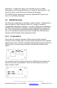
2.1.1 Connections
One end of the receiver features a SMA reverse polarity antenna
connector and a 5.08mm pitch 3 position plug receptacle for the optional
speed sensor input. With the standard analog output expansion board, a
3.81mm pitch 2 position plug receptacle provides the analog output
signal.
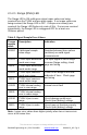
The opposite end has a high insertion force USB type B receptacle for
power and serial communication. Near the USB connector are four
green indicator LEDs.