
User's Guide

This document is subject to change without prior notification.
Binsfeld Engineering Inc. | 231-334-4383 www.binsfeld.com 869610-9_A2 Pg. 42
Shunt Calibration
The more common method is to perform a shunt calibration. This
method takes into account deviations in the setup from the strain gage to
the transmitter, but unlike a deadweight calibration, none of the
deviations in the physical parameters.
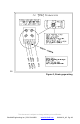
The easiest way to conduct a shunt calibration is by enabling one of the
reference shunt resistors on-board the TX20K. An internal precision
resistor is placed in parallel with one arm of the bridge to simulate a
precise strain value. As stated earlier, Reference 1 simulates 100
microstrain (µe) and Reference 2 simulates 500 µe when using a 350
Ω
strain gage with a Gage Factor of 2.0. Alternatively, precision resistors
can be placed in parallel with one arm of the bridge to simulate a torque
load. The Tech Info section on our website (www.binsfeld.com) has a
helpful Torque Strain Calculator to assist in determining the strain a
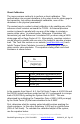
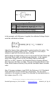
given resistor value simulates. The equation relating strain and shunt
resistance is shown below:
Legend of Terms
R
C
Shunt Calibration Resistance (kΩ)
R
G
Gage Resistance (Ω)
N
Number of Active Gages
GF
Gage Factor
ε
Strain (µe)
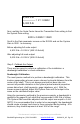
In the example from Steps 1 & 2, the Full Scale Torque is 4,901 ft-lb and
the RX20K output has been scaled so that 10 V corresponds to a torque
load of 5,000 ft-lb by setting the System Gain to 3920. This was
determined by multiplying the Transmitter Gain of 4000 (±500 µe range)
by the Scale Factor (Z) that was calculated to be 0.9802.
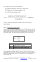
First, determine what the system output should be when applying the
shunt resistance. In this case, Reference 1 (100 µe) is a good choice
(20% of Full Scale). To calculate the calibrated output of the system,
use the equation below:
R
G
R
C
= ───────
(N)(GF)(ε)