
User's Guide


This document is subject to change without prior notification.
Binsfeld Engineering Inc. | 231-334-4383 www.binsfeld.com 869610-9_A2 Pg. 30
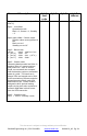
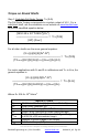
Command Description
byte0
cmd
code
byte1
byte2
byte3
chksum
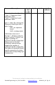
Speed input configuration
byte1 – Speed input
configuration
b7:b4 - #bits to right
shift sync timer
value.
b3:b0 - #bits to right
shift speed timer
value.
Speed timer measures the period
between negative speed input
edges.
Sync timer measures the time
from the start of the previous
block message to the first
negative speed input edge.
0x60
0x00
chksum
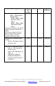
Receiver RF transmit power
control
byte1 - RF power level to
set (0 to 14)
0x61
0x00
chksum
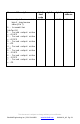
Receiver RF channel control
byte 1 – RF channel to
set (0 to 15)
value = RF channel (1 to
16) – 1,
add 128 to value for
multiple transmitters
(in other words, set bit 7
of byte 1)
0x62
0x00
chksum