
User's Guide


This document is subject to change without prior notification.
Binsfeld Engineering Inc. | 231-334-4383 www.binsfeld.com 869610-9_A2 Pg. 19
4.2 Bench Testing
1. Connect Receiver Antenna to Antenna connector on the rear
panel of the RX20K Receiver. Position magnetic-mount antenna
with element installed near the TX20K, typically within 10 feet (3
meters).
2. Use a USB A male to B male cable to connect the RX20K to a
computer for power and communications. The TT20K
Configuration and Monitoring LabVIEW program must already be
installed on the computer as explained in the 818006-9 TT20K
Configuration and Monitoring User's Guide.
NOTE: If the RX20K was previously configured and only the
analog output (no serial data) is being used, any USB power
source with a minimum of 250mA output capability can be used
to power the RX20K.
3. Attach 9V Battery Connector to TX20K Transmitter (red to
+PWR, black to –PWR). Attach BS900 Bridge Simulator to the
TX20K terminals +/- EXC and +/- SEN to coincide with pins on
BS900. Clip 9V battery to connector.
4. If the TX20K and RX20K are not already communicating, use the
Configuration and Monitoring program to establish
communications between them. Verify adequate signal strength.
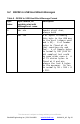
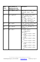
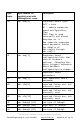
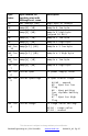
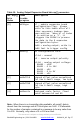
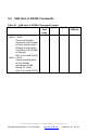
5 Communications Protocol
5.1 General USB Host to RX20K Communications
The RX20K uses a FTDI chips FT230XS USB interface. PC software
drivers are available on the FTDI chips web site
http://www.ftdichip.com/FTDrivers.htm. The Binsfeld Engineering TT20K
Configuration/Monitoring LabVIEW program requires the FTDI VCP
driver for the operating system used (typically Windows 32bit).
Serial communications settings are 1M baud, 8 bits, odd parity, 1 stop
bit, RTS/CTS flow control.