
User's Guide

This document is subject to change without prior notification.
Binsfeld Engineering Inc. | 231-334-4383 www.binsfeld.com 869610-9_A2 Pg. 11
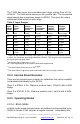
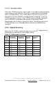
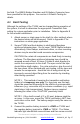
The TX20K has seven user selectable input range settings from ±0.2 to
±20mV/V. The table below shows just the positive side. The transmitted
signal sample has a maximum range of ±20000. This gives the output
resolutions listed below for each range.
Table 3, Input Ranges
Input
Range
mV/V
1
Input
Range
µe
2
Output
Resolution
µe/lsb
2
Output
Resolution
µV/V/lsb
Output
Shunt1
3
100µV/V
Output
Shunt2
3
1mV/V
0.2
100
0.005
0.010
10000
over-range
0.5
250
0.0125
0.025
4000
over-range
1
500
0.025
0.050
2000
20000
4
2
1000
0.05
0.10
1000
10000
5
2500
0.125
0.25
400
4000
10
5000
0.25
0.5
200
2000
20
10000
0.5
1
100
1000
1
These are the absolute maximum input values (±). If the expected input levels are close
to these, the next larger input range should be selected. This will give some overhead for
the signal span and gage offset.
2
Microstrain with a Gage factor = 2.00.
lsb = least significant bit of the output (transmitted) sample value.
3
The shunt values shown are for a 350
Ω gage
4
This shunt value is right at full scale and could cause an over-range condition
2.2.4 Internal Shunt Resistors
There are two internal shunt resistors for calibration that can be enabled
and disabled individually by the RX20K.
Shunt 1 is 875KΩ, 0.1%, 10ppm to produce Vout = 100µV/V with a 350Ω
bridge.
Shunt 2 is 87370Ω, 0.1%, 10ppm to produce Vout = 1mV/V with a 350Ω
bridge.
2.2.5 Operating Modes
2.2.5.1 Block Mode
In Block mode torque measurements are buffered and transmitted to the
RX20K in blocks of 100 samples at regular intervals. Immediately after