B8 8125 TECHNICAL MANUAL.
INTRODUCTION. BILSTEIN introduced the very first monotube gas pressure shock absorber to the extremely challenging world of off-road racing and it didn’t take long for racers to recognize the superior performance this new technology provided. With no emulsion and no foam cells, the BILSTEIN monotube provides consistent damping for ultimate vehicle control in even the roughest terrain.
GETTING STARTED. ! Prior to getting started, please read the information below as it is important to maintaining the life and performance of your shocks. Do not attempt to disassemble or assemble your shocks without proper tools or technical knowledge. OWNER REBUILDABLE The B8 8125 Series are fully owner rebuildable and revalvable. Any component can be purchased through a BILSTEIN dealer or direct from BILSTEIN. Owner rebuildable shocks can also be revalved and serviced by BILSTEIN.
COILOVER HARDWARE B8 8125 Series are equipped with dual-rate spring hardware on most models. This consists of a bottom spring hat, a spring slider, (2) spring crossover nuts, and an upper spring seat. The spring seat and the spring crossover nuts are installed in the proper orientation. SPRING SEAT The upper spring seat is threaded and can be used to adjust spring preload. Rotating the spring seat clockwise will increase preload (lift), while rotating counter clockwise will decrease preload (lower).
WARRANTY LIMITED 90 DAY WARRANTY BILSTEIN warrants to the original retail purchaser that, for a period of ninety (90) days from the date of purchase, this product shall be free from defects in material and workmanship. Any implied warranty of merchantability, fitness or fitness for particular purpose, except as may be prohibited by applicable law, is likewise limited in duration to ninety (90) days from the date of original retail purchase.
TABLE OF CONTENTS. B8 8125 Components Illustration.............................. 8 Illustration......................................................... 8 Components..................................................... 9 Technical Guide.................................................... 10 Seal Kits - 60mm | 46mm................................. 11 Piston Rod Assembly Removal........................... 12 Rod Guide Reseal.............................................
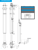
B8 8125 COMPONENTS ILLUSTRATION 25 25 17 2 3 22 21 Item # Description 22mm x 60mm Rod Guide Assembly 1 Rod Guide Housing 2 O-Ring 3 Rod Seal, 22mm 4 Seal, single step w/ O-Ring 5 Rod Guide Bushing 22x20mm 22mm x 46mm Rod Guide Assembly 1 Rod Guide Housing 2 O-Ring 3 Rod Seal, 22mm 4 Seal, single step w/ O-Ring 5 Rod Guide Bushing 22x20mm 18 1 QTY.
B8 8125 COMPONENTS Item # Description Part # (60mm) Shock Components 1 Tube See Table A 2 End Cap E4-LG0-Z025A00 3 O-Ring 1000406 4 Piston Rod See Table A 5 Piston Band E4-KR2-Z017A00 6 Piston Nut E4-MU1Z015A01 7 Internal Spacer E4-RO3-Z111A03 8 Rod Guide Assy.
TECHNICAL GUIDE. ! WARNING! Please review complete manual before beginning any disassembly.
SEAL KITS 60MM | 46MM. Before starting, you must determine if you have a 60mm or 46mm shock (refer to section: How to Measure Your Shock Absorber, page 4) and purchase the appropriate seal kit. Seal kits include all rod guide seals and reservoir components.
PISTON ROD ASSEMBLY REMOVAL. STEP 1 STEP 2 Place shock upside down in vise and clamp on eyelet. Using pick, release all gas pressure and remove SchraderTM core. ! Use a buffering layer between the clamp and eyelet, such as a towel, to avoid scratching the anodized end cap. IMPORTANT! Do not collapse the piston rod once the gas pressure is extinguished. STEP 3 STEP 4 Using a 3mm socket head wrench, remove the 3 socket head screws from the rod guide.
PISTON ROD ASSEMBLY REMOVAL STEP 5 STEP 6 Depress rod guide down revealing the snap ring. Using a pick, remove the snap ring from inside the shock body. Snap Ring STEP 7 Carefully remove piston rod assembly from the shock body. If the assembly cannot be pulled out of the shock body by hand, place a 5/8” round pry bar horizontally into the eyelet and use a hammer to strike the pry bar upwards.
ROD GUIDE RESEAL. Before starting, you must determine if you have a 60mm or 46mm shock (refer to section: How to Measure Your Shock Absorber, page 4) and purchase the appropriate seal kit. Seal kits include all rod guide seals and reservoir components (shown on page 11). 60mm Seal Kit: Part# B4-KT0-Z024A01 46mm Seal Kit: Part# B4-KT0-Z023A01 46mm Rod Guide Seals 60mm Rod Guide Seals STEP 1 STEP 2 Clamp rod end in vise. Remove rod nut using 3/4” socket or open-end wrench.
ROD GUIDE RESEAL STEP 3 STEP 4 Remove valving discs and piston from rod. Remove rod guide from piston rod. ! IMPORTANT! To maintain performance, it is imperative that the valve discs and components are removed and replaced in the precise order that they were removed. We suggest laying out the compression valve stack, piston, and rebound valve stack in order. STEP 5 STEP 6 Remove wiper cap from piston rod. Using a pick, remove all five seals from the rod guide and wiper cap.
ROD GUIDE RESEAL STEP 6 - CONTINUED STEP 7 Install o-ring (brown) in lower groove inside rod guide. O-Ring STEP 8 STEP 9 On the high pressure step seal, identify the step. Making sure the smallest ID of the step faces up, bend the high pressure step seal and carefully install in same lower groove, covering the brown o-ring in step 7. High pressure seal shown upside-down to illustrate the different steps and internal diameters(IDs).
ROD GUIDE RESEAL STEP 10 STEP 11 Identify the location of the groove on the cup seal. Install cup seal with groove portion facing down. Illustrated groove will be installed inside the rod guide facing down. Fold seal in the middle and carefully install in upper groove. STEP 12 STEP 13 Install wiper seal in wiper cap. Coat external o-ring with white lithium grease and install in outer groove of rod guide.
PISTON WEAR BAND REPLACEMENT. Before starting, you must determine if you have a 60mm or 46mm shock (refer to section: How to Measure Your Shock Absorber, page 4) and purchase the appropriate wear band: 60mm Piston: E4-AK1-Z050A00 Wear Band: E4-KR2-X017A00 46mm Piston: E4-B46-205NDT Wear Band: E4-KR2-X001A02 STEP 1 STEP 2 Remove old wear band using a pick. Install new wear band.
ROD GUIDE AND VALVING INSTALLATION. STEP 1 STEP 2 Install wiper cap on piston rod. Lightly lubricate the inside of the rod guide with white lithium grease and install the rod guide on the piston rod. STEP 3 STEP 4 Install valving discs and piston on the piston tennon in the order that it was removed in step 3 of section: Rod Guide Reseal, page 15. Place a dab of 271 red Loctite on rod nut and install. Torque to 250 inch pounds.
DRAINING THE OIL. STEP 1 Remove the shock body from the vise and drain oil into oil safe container. ! Please obey all environmental regulations when disposing of oil. Raise reservoir higher than the shock body to drain all the oil contents from both the reservoir and shock body.
RESERVOIR RESEAL DISASSEMBLY. ! WARNING! Must release gas pressure and complete section Piston Rod Assembly - Removal, page 12-13, before continuing. STEP 1 STEP 2 Place shock body upside down in vise and clamp on eyelet. Remove reservoir hose from shock body using a 7/8” open-end wrench. Once the nut is loose, continue to unscrew by hand. Use a buffering layer between the clamp and eyelet, such as a towel, to avoid scratching the anodized end cap.
RESERVOIR RESEAL - DISASSEMBLY STEP 5 STEP 6 Remove inner snap ring using pick. Remove cap. Screw hose onto the fitting, hand tighten, and pull up. STEP 7 Turn reservoir upside-down in vise and depress Schrader end cap revealing inner snap ring. If the SchraderTM end cap will not move when depressing by hand, use a rubber mallet and lightly tap to depress. 22 STEP 8 TM Remove inner snap ring using pick.
RESERVOIR RESEAL - DISASSEMBLY STEP 9 Turn reservoir right-side up and lightly clamp in vise. Using the rubber mallet handle, begin tapping the dividing piston down. This will remove the SchraderTM valve end cap and the dividing piston from the reservoir. ! If the rubber mallet handle is not long enough, use a piece of PVC pipe that is the correct length.
RESERVOIR RESEAL - DISASSEMBLY STEP 12 STEP 13 Remove wear band from dividing piston. Remove o-ring from reservoir end cap using pick.
RESERVOIR RESEAL ASSEMBLY. Before starting, you must determine if you have a 60mm or 46mm shock (refer to section: How to Measure Your Shock Absorber, page 4) and purchase the necessary components. All seals and components are included in the seal kits shown on page 11, or can be purchased separately using part numbers below.
RESERVOIR RESEAL - ASSEMBLY STEP 3 STEP 4 60mm - Install new wear band on dividing piston. 60mm - Install new o-ring on dividing piston. Use white lithium grease on o-ring to aid in installation. STEP 5 STEP 6 46mm & 60mm - Install dividing piston in shock with the wear band towards the nitrogen chamber (facing down). Position the dividing piston inside the nitrogen chamber according to the chart below. This step is critical to ensure the nitrogen chamber has the proper volume.
RESERVOIR RESEAL - ASSEMBLY STEP 7 Install reservoir end cap in reservoir tube and depress downwards so it is right below the inner snap ring groove. STEP 8 Install inner snap ring and confirm it is seated properly inside snap ring groove. STEP 9 STEP 10 Install hose on reservoir end cap and hand tighten. Grasping the hose, pull end cap towards snap ring. Inspect assembly to assure the snap ring is properly seated.
RESERVOIR RESEAL - ASSEMBLY STEP 11 STEP 12 Tighten hose using two 7/8” box wrenches. Flip the reservoir upside-down in vise and install SchraderTM end cap so that it is positioned right below the inner snap ring. ! IMPORTANT! Make sure the SchraderTM core is removed. STEP 13 Install inner snap ring and confirm it is seated properly inside snap ring groove.
FILLING THE OIL. STEP 1 STEP 2 Placing shock body upside down in vise, attach reservoir hose and tighten using a 7/8” box wrench. Fill oil into open end of the shock body. Use the proper oil volume by referencing the chart on page 41. Use a buffering layer between the clamp and eyelet, such as a towel, to avoid scratching the anodized end cap. STEP 3 Loosen vise and lean shock at an approximate 10 degree angle and retighten vise. Allow several minutes for the air bubbles to surface and dissipate.
INSTALLING THE PISTON ROD. STEP 1 Coat the o-ring on the rod guide with white lithium grease and with the piston rod fully extended, carefully push piston and rod guide into the shock body. It is OK if oil purges out the side vent of the rod guide. Rod guide vent STEP 2 STEP 3 Install internal snap ring and confirm it is seated properly inside snap ring groove. Pull up on rod guide to properly seat against the snap ring.
INSTALLING THE PISTON ROD STEP 4 STEP 5 Slide down wiper cap and align the 3 holes. Using a dab of 271 red Loctite, install the 3 screws and tighten with 3mm socket head wrench.
PRESSURIZING THE SHOCK ABSORBER. STEP 1 STEP 2 Install Schrader Core. TM Pressurize with nitrogen to desired level. ! 32 IMPORTANT! B8 8125 Series are delivered with 200 PSI nitrogen pressure. Proper fill level range is from 180-200 PSI.
REVALVING. STEP 1 STEP 2 Remove piston rod assembly from shock body and fasten rod end in vise. (Refer to the section: Piston Rod Assembly Removal, page 12) Remove 3/4” rod nut using a open end wrench. Use a buffering layer between the clamp and rod end, such as a towel, to avoid scratching the rod end. STEP 3 Carefully lay out valving on a clean surface in the order it was removed.
REVALVING STEP 4 Determine which valve plates need to be changed and exchange plates in the layout. It’s always a good practice to measure each shim to assure proper valving. In addition, utilizing a valving worksheet will help keep track of changes. See page 46 for a usable valving worksheet. STEP 5 STEP 6 Clean piston rod tennon with a clean dry towel. Reinstall valve plates on piston rod tennon in the order that they were removed.
REVALVING STEP 7 STEP 8 Place a dab of 271 red Loctite on piston rod nut. Install piston rod nut and torque to 250 inch pounds. STEP 9 Carefully reassemble piston rod assembly in shock body.
HEIM REPLACEMENT. STEP 1 STEP 2 Using snap ring pliers, remove snap ring from both sides on the rod end. Using table press, remove heim joint. Two sockets may be used on either side of the rod end to remove heim joint using a table press. The lower socket must be large enough for the heim to drop into. STEP 3 STEP 4 Reinstall snap ring on one side of the rod end. Install new heim in eyelet.
HEIM REPLACEMENT STEP 5 Reinstall second snap ring.
ROD END REMOVAL & REPLACEMENT. STEP 1 STEP 2 Place piston rod in a hydraulic press using a clean radius or triangle aluminum soft jaw. Using torch, heat up the rod end where it meets the piston rod. This will loosen the red Loctite and allow for the rod end to spin easier. It is ok for the shock to be fully assembled, with the exception of springs/seats, when replacing the rod end. STEP 3 STEP 4 Using an adjustable open end wrench (or similar) rotate the eyelet counter clockwise and remove.
CHANGING THE HOSE. ! WARNING! Release gas pressure and complete section Piston Rod Assembly - Removal, page 12-13, before continuing. STEP 1 STEP 2 Remove piston rod assembly from shock body. (Refer to the section: Piston Rod Assembly Removal, page 12) Drain shock oil. (Refer to the section: Draining the Oil, page 20) STEP 3 STEP 4 Remove reservoir hose from shock body using 7/8” box wrench. Remove hose from reservoir end cap using (2) 7/8” box wrenches.
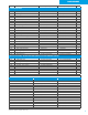
VALVING CHART. 46mm Valve Stacks Rebound / Compression Brake Support#4 Support#3 Support#2 Support#1 Cover Disc Bypass Piston Bypass Cover Disc Support#1 Support#2 Support#3 Support#4 Support#5 Brake 360/80 20X3.0 19X50 22X40 28X40 32X40 37.4X40 18X10 U37T PISTON 18X15 37.4X30 32X30 28X30 22X50 17X50 17X50 B46-22 275/78 20X3.0 18X50 22X50 28X40 32X35 37.4X35 18X10 U37T PISTON 18X15 37.4X30 32X25 28X20 22X50 17X50 17X50 B46-22 Rebound 255/100 20X3.0 19x50 22X50 28X40 32X30 37.
OIL VOLUME CHART. Part # Description B8 8125 - 46mm (2.0") Oil Volumes 33-225463 46mm Coilover W/ Reservoir, 5" Stroke 33-225487 46mm Coilover W/ Reservoir, 6" Stroke 33-225500 46mm Coilover W/ Reservoir, 8" Stroke 33-225524 46mm Coilover W/ Reservoir, 10" Stroke 33-225548 46mm Coilover W/ Reservoir, 12" Stroke 33-225562 46mm Coilover W/ Reservoir, 14" Stroke 33-225586 46mm Coilover W/ Reservoir, 16" Stroke B8 8125 - 60mm (2.
PARTS LIST.
PARTS LIST Part # Description Reservoirs and Components continued... 25250129 Cap: Schrader Valve 1001025 Adapter: O-Ring Port to -8 Male JIC 2021-8-8S Adapter: 1/2" Pipe to -8 Male JIC Wear Bands E4-KR2-X001A02 Wear Band: 46mm(2.0") Working Piston E4-KR2-X017A00 Wear Band: 60mm(2.
PARTS LIST Part # Valve Discs E4-FE1-Z009A76 E4-FE1-Z009A02 E4-FE1-Z009A73 E4-FE1-Z009A43 E4-FE1-Z009A72 E4-FE1-Z009A44 E4-FE1-Z009A74 E4-FE1-Z009A00 E4-FE1-Z009A01 E4-FE1-Z009A06 E4-FE1-Z009A97 E4-FE1-Z009A10 E4-FE1-Z009A08 E4-FE1-Z009A09 E4-FE1-Z009A07 E4-FE1-Z009A46 E4-FE1-Z009B41 E4-FE1-Z009A49 E4-FE1-Z009A04 E4-FE1-Z009A05 E4-FE1-Z009A03 E4-FE1-Z009A39 E4-FE1-Z009A50 E4-FE1-Z009A40 E4-FE1-Z009A32 E4-FE1-Z009A51 E4-FE1-Z009A34 E4-FE1-Z009A98 E4-FE1-Z009A82 E4-FE1-Z009A11 E4-FE1-Z009A38 E4-FE1-Z009A47 E
PARTS LIST Part # Valve Discs continued...
VALVING TRACKING WORKSHEET.
NOTES.
BILSTEIN Off-Road Racing Department 14102 Stowe Drive | Poway, CA 92064 (800) 537-1085 thyssenkrupp Bilstein of America marketing@bilsteinUS.com www.bilsteinUS.com Printed in the USA ©2015 4.2016 / Subject to technical modifications. Misprints and errors excepted.