
Owners manual


E4-WM5-Y566A00
MOUNTING INSTRUCTION
created: 03.07.17 E4-WM5-Y566A00_0 page 7 of 10 latest revision:
Supplemental Mounting Instructions:
1. Refer to the instructions above; disregard steps F, H, I, J, and L. Instead, complete the procedure
described below.
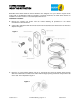
2. Discard the M8 hardware shown here:
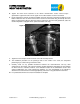
3. The upper hole on the frame is 0.35” in diameter. It must be drilled out to 0.39” using a 25/64" drill bit
(not provided).
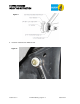
4. If you have access to a nutsert gun or pliers, that may be preferable to set the provided nutsert.
Otherwise, using the items in the supplemental hardware kit, and a ½” box end wrench, arrange them
as shown and turn the ¼”-20 screw by hand until it is snug.
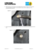
Note that the screw will pass through the serrated flange nut without engaging the threads. The threads
will instead engage the nutsert. The serrations on the flange nut prevent the nutsert from rotating
while setting it.
Figure 10
Figure 9