
Owners manual


E4-WM5-Y566A00
MOUNTING INSTRUCTION
created: 03.07.17 E4-WM5-Y566A00_0 page 6 of 10 latest revision:
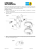
R. Tighten the lower mount fasteners to the vehicle manufacturer’s service manual torque
specification. Tighten the locknut on the upper mount until it bottoms out on the last thread.
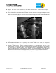
S. Figure 8 depicts the reservoir and shock installed. Orient the reservoir so that the hose fitting is on the
bottom. Route the hose as shown and secure the reservoir to the bracket using the clamps. The hose
fittings are designed to swivel to allow the reservoir and hose to be more easily positioned. (Note: the
reservoir depicted is equipped with an optional Schrader valve cap.)
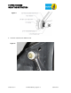
T. Tighten the hose clamps until the reservoir cannot be manually rotated.
U. The installation procedure for the passenger side of the vehicle is the same, the component
positioning is just a mirror image of the driver side.
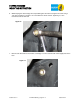
V. Carefully check for any possible interference between the reservoirs/hoses and any other
components on the vehicle. The reservoir mounting location depicted is appropriate for most vehicles
for which this kit is intended, however, some wheel/tire and/or lift kit combinations and/or other
vehicle modifications may create interference problems. It is the responsibility of the installer to
determine if the reservoirs are mounted appropriately and if there is any potential for interference.
W. If no potential interference is found, the installation is complete.
Figure 8