
Owners manual

E4
E4E4
E4
-
--
-
WM5
WM5WM5
WM5
-
--
-
Y
YY
Y
48
4848
48
9
99
9
A00
A00A00
A00
MOUNTING I
MOUNTING IMOUNTING I
MOUNTING I
N
NN
N
STRUCTION
STRUCTION STRUCTION
STRUCTION
created: 06.12.15 E4-WM5-Y489A00_0 Page 2 of 4 latest revision:
IMPORTANT!
Installation of shock absorbers requires special tools and expert knowledge. Accordingly, installation of all BILSTEIN
products must be performed by a qualified suspension specialist.
Always use a chassis hoist for the installation of BILSTEIN products and make certain that the raised vehicle is securely
attached to the hoist and/or supported to prevent the vehicle from slipping, falling, or moving during the installation
process.
If you choose to install any BILSTEIN product without the necessary special tools, expertise or
chassis hoist, you
may subject yourself to the risk of serious bodily injury or death. If you elect not to use a chassis hoist, at least
make sure the vehicle is on level ground, that all tires on the ground during installation are blocked to prevent movement,
and that adequately secured safety stands (jack stands) are used to support the chassis. NEVER get under the vehicle
until you have checked to make sure all of these steps are performed.
CAUTION!!
Before disassembling the front suspension, refer to the vehicle manufacturer’s Service Manual for
proper procedures. The coil spring is preloaded and must be compressed with a spring compressor
to release load before the upper mount is disassembled. Failure to follow the vehicle manufacturer’s
procedures may cause serious injury or death, and may damage the vehicle.
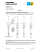
Instructions for assembly of front shock absorber module:
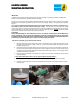
1.
Install the spring seat onto the shock body as shown. Ensure that the groove inside the spring seat fits over
the circlip on the shock body (see page 1 detail (A)). The dust boot and boot adapter will need to be removed
to slide the spring seat on.
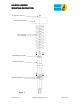
2.
Re-install the dust boot and boot adapter onto the stem of the rod as shown. The boot adapter is clipped into
the top of the dust boot. Install OE coil spring and re-install all original mount parts in reverse order of removal
in accordance with the vehicle manufacturer’s Service Manual. Please refer to Figure 1 for the proper order of
installation of the module components.
3.
Install new lock nut and tighten until it bottoms out. Torque lock nut to vehicle manufacturer’s service manual
torque specification.
***
Only continue with Steps 4 and 5 if you are using the highest ride height setting***
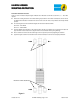
4.
Remove original chassis jounce bumpers (two per side) according to vehicle manufacturer’s procedures.
5.
Install the new spacer washers as shown and reinstall the jounce bumpers in their original positions. Torque to
27 Nm (20 lb-ft).