
Owners manual


E4
-
WM5
-
Y
485
A00
MOUNTING I
N
STRUCTION
created: 06.02.15 E4-WM5-Y485A00_1 Page 2 of 4 latest revision: 08.22.17
IMPORTANT!
Installation of shock absorbers requires special tools and expert knowledge. Accordingly, installation of all BILSTEIN products must
be performed by a qualified suspension specialist.
Always use a chassis hoist for the installation of BILSTEIN products and make certain that the raised vehicle is securely attached to
the hoist and/or supported to prevent the vehicle from slipping, falling, or moving during the installation process.
If you choose to install any BILSTEIN product without the necessary special tools, expertise or
chassis hoist, you may
subject yourself to the risk of serious bodily injury or death. If you elect not to use a chassis hoist, at least make sure the
vehicle is on level ground, that all tires on the ground during installation are blocked to prevent movement, and that adequately
secured safety stands (jack stands) are used to support the chassis. NEVER get under the vehicle until you have checked to make
sure all of these steps are performed.
CAUTION!!
Before disassembling the front suspension, refer to the vehicle manufacturer’s Service Manual for proper
procedures. The coil spring is preloaded and must be compressed with a spring compressor to release load
before the upper mount is disassembled. Failure to follow the vehicle manufacturer’s procedures may cause
serious injury or death, and may damage the vehicle.
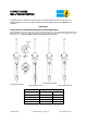
Instructions for assembly of front shock absorber module:
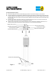
1.
Install the spring seat onto the shock body as shown. Ensure that the groove inside the spring seat fits over the circlip on
the shock body (see page 1 detail (A)). The dust boot and boot adapter will need to be removed to slide the spring seat
on.
2.
Re-install the dust boot and boot adapter onto the stem of the rod as shown. The boot adapter is clipped into the top of
the dust boot. Install OE coil spring and re-install all original mount parts in reverse order of removal in accordance with
the vehicle manufacturer’s Service Manual. Please refer to Figure 1 for the proper order of installation of the module
components.
3.
Install new lock nut and tighten until it bottoms out. Torque lock nut to vehicle manufacturer’s service manual torque
specification.
** Ride heights indicated are typical. Actual ride height is influenced by which factory suspension the vehicle is equipped with
and its condition; optional equipment and accessories on your vehicle, and other vehicle modifications such as replacement coil
springs, wheel and tire combinations, etc.
Modifying/lifting the suspension to your vehicle may raise its center of gravity and may make it more susceptible to loss of
control and/or rollover, which may result in death or serious injury. We strongly recommend that you offset the loss of rollover
resistance as much as possible by increasing tire track width, and that you equip the vehicle with a functional roll bar and cage
system.
Wear seat belts and shoulder harnesses at all times, and avoid situations where a side rollover may occur.