
Owners manual

E4
E4E4
E4
-
--
-
WM5
WM5WM5
WM5
-
--
-
Y
YY
Y
547
547547
547
A0
A0A0
A0
0
00
0
MOUNTING I
MOUNTING IMOUNTING I
MOUNTING I
N
NN
N
STRUCTION
STRUCTION STRUCTION
STRUCTION
created: 10.14.2016 E4-WM5-Y547A00_0 Page 5 of 5 latest revision:
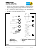
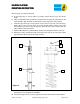
Refer to Figure 4 for steps G through K.
G.
Fit the bump stop (7) over the piston rod, leaving it flush with the top of the chrome
length.
H.
Using an appropriate spring compressor, compress the coil spring (8) and install it on the
shock absorber. Align the lower coil end with end of the ramp on the spring seat (9).
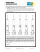
I.
Install the upper mount (6) over the piston rod end and on to the top of the coil spring.
Rotate upper mount so that its studs are in their original position relative to the lower
mount bearing (as noted in step A). Align the upper coil end of the coil spring with the
rubber isolator in the upper mount.
J.
Install the M12 Washer (1) and the M12x1.5 locknut (2) and tighten to 45 N·m (34 lb·ft).
K.
Release the spring compressor while ensuring that the ends of the coil spring remain
aligned with the spring seat (8) and upper mount (6).
L.
Install assembly on to the vehicle and tighten all fasteners to vehicle manufacturer’s
specifications. This completes the installation.
M.
Check wheel alignment. If necessary, adjust to the vehicle manufacturer’s specifications.
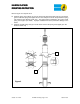
Figure 4
2
9
7
8
6
1