
Product Manual


WWW.BIGASSFANS.COM © 2015 DELTA T LLC ALL RIGHTS RESERVED.
18
MOUNTING STRUCTURE: I-BEAM
WARNING: The fan should not be installed unless the structure on which the fan is to be mounted is
of sound construction, undamaged, and capable of supporting the loads of the fan and its method of
attachment. Verifying the stability of the mounting structure is the sole responsibility of the customer and/
or end user, and Big Ass Fans hereby expressly disclaims any liability arising therefrom, or arising from
the use of any materials or hardware other than those supplied by Big Ass Fans or otherwise specified in
these installation instructions.
CAUTION: Do not fasten the I-Beam mount to vertical I-beams, i.e., I-beams serving as columns.
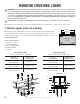
Depending on the size of your I-beam, the Yoke Mount kit comes with either a small or large upper yoke.
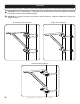
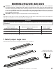
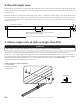
1. Attach upper yoke (to I-beam)
Measure the flange width of the I-beam. Consult the tables and diagram below.
Select the upper yoke mounting holes that match the flange width of the I-beam.
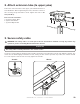
Secure the upper yoke to the I-beam with the Yoke Hardware. Tighten the bolts
to 40 ft·lb (54.2 N·m).
Upper Yoke Hardware:
a. (4) 1/2-13 x 2” Bolt
b. (8) 1/2” Flat Washer
c. (4) 1/2-13 Nylock Nut
d. (2) Beam Clamp
e. (2) Spacer
Side View
b
a
c
b
e
d
Small Upper Yoke
13-3/4’’ (349 mm) x 10” (258 mm)
I-beam
flange width
Upper yoke
mounting holes
5” (127 mm) to
6-5/8” (168 mm)
Inner holes
> 6-5/8” (168 mm) to
8-1/4” (210 mm)
Middle holes
> 8-1/4”(210 mm) to
9-7/8”(250 mm)
Outer holes
Large Upper Yoke
18-1/2’’ (470 mm) x 10” (258 mm)
I-beam
flange width
Upper yoke
mounting holes
9-7/8” (250 mm) to
11-3/8” (289 mm)
Inner holes
> 11-3/8” (289 mm) to
13” (330 mm)
Middle holes
> 13” (330 mm) to
14-5/8” (371 mm)
Outer holes
outer holes
middle holes
inner holes
Upper Yoke
(top view)