
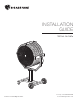
Product Manual


WWW.BIGASSFANS.COM © 2015 DELTA T LLC ALL RIGHTS RESERVED.
4
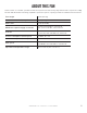
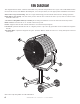
FAN DIAGRAM
The diagram below shows a Yellow Jacket with one pedestal and portable base. If you ordered the Wall/Column
mount, Yoke mount, Yoke Washer Assembly kit, or an extra pedestal, see the appropriate installation instructions.
A. Protective Cage and Housing. The steel cage and housing protect both the fan and users during operation.
B. Fan Motor (not shown). The fan motor powers the fan and controls the fan’s speed, and is located on the
backside of the fan.
C. Position Locking Mechanism (not shown). The locking mechanism secures the fan in the desired position.
D. Fan Control. Turns the fan on or o and controls fan speed.
E. Yoke. Supports the fan and includes handle for use when transporting fan.
F. Pedestal. Optional. Extends the fan to a higher position. Up to two (2) pedestals can be installed to heighten
the fan.
G. Portable Base. Optional. Supports the yoke and fan. Wheels allow the fan to be easily transported around
workspace.
Note: Fan setup may dier from the illustration.