
Hardware manual


Electra Elite Issue 8
System Hardware Manual 8 - 45
2. Set CT(A)-R Unit switches to default settings. Refer
to Table 8-4 CT(A)-R Unit Switch Settings.
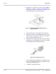
3. Hook tabs A and B in the slots on the Multiline
Terminal as shown in Figure 8-59 Attaching the
CT(A)-R Unit to the DTH/DTR Multiline Terminal,
and press down until the unit clicks into place.
4. Install the extended base cover.
Table 8-4 CT(A)-R Unit Switch Settings
Switch Setting/Description
SW1 1 (default)
SW3–1
Sets impedance to 600 for devices such as
modems or facsimile machines.
SW3–2
Used for complex impedance devices such as
Single Line Telephones.
DSW
Figure 8-59 Attaching the CT(A)-R Unit to the DTH/DTR
Multiline Terminal