
Hardware manual


Issue 8 Electra Elite
8 - 38 Installing Electra Elite IPK and D
term
Series i Equipment
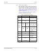
Table 8-2 AD(A)-R Cable Connections
Terminal
Number
Cables to Connect Terminal Specifications
T1
T2
When warning tone is not being sent from
the recorder, connect wire pair input from
tone generator to T1:T2. The warning
tones from the generator are sent to T1:T2
on a dedicated wire pair while the speech
path is sent from the Input/Output
Terminal:
Refer to dip switch settings in Table 8-1
AD(A)-R Unit Switch Settings. on T3:T4
over a separate wire pair to the recorder.
Input Terminal:
T1 and T2 are enabled for tone generating device
when DSW switches 3 and 4 are OFF.
(When DSW switches 3 and 4 are ON, a humming
sound may be recorded due to impedance
mismatch.)
Input Impedance on T1 and T2: 100K
Input Level on T1 and T2: –15 dB ~ 40 dB
T3:T4
Connect recorder device wire pair speech
input to T3:T4.
When the recorder used supplies a
warning tone, this tone may also be sent
over the T3:T4 wire pair back to the
terminal.
Input/Output Terminal:
Refer to dip switch settings in Table 8-1 AD(A)-R
Unit Switch Settings.
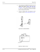
T5
Connect the bare end of the control cable. When a Multiline Terminal is idle, this contact is
closed. When the Multiline Terminal goes off-hook
(using the handset, headset, or speakerphone), this
contact is open.
When recorder owner manual specifies start on
open circuit, connect T5 and T6.
T6
Connect the shielded end of the control
cable.
Provides common connection for control cable.
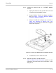
T7
Connect the bare end of the control cable. When the Multiline Terminal is idle, this contact is
open. When the Multiline Terminal is busy (using
the handset, headset, or speakerphone), this
contact is closed.
When recorder owner manual specifies start on
closed circuit, connect T6 and T7.
T8 Unused
T9 Unused
REC
Jack
Connect recorder device wire pair speech
input to REC Jack.
When the recorder used supplies a
warning tone, this tone may also be sent
through the REC Jack wire pair back to the
terminal.
Input/Output Terminal:
Refer to dip switch settings in Table 8-1 AD(A)-R
Unit Switch Settings.