
Hardware manual


Electra Elite Issue 8
System Hardware Manual 8 - 33
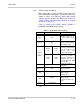
14.2.1 Switch Settings and Wiring
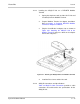
When voice calls are only recorded, Remove the cover
for the DSW Switch with nippers, and set the switches as
shown in Figure 8-44 AD(A)-R Switch With Default
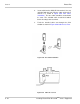
Settings and wire between the AD(A) and recorder as
shown in Figure 8-46 DSW Switch Settings for Sending
Voice Calls to Terminal.
Table 8-1 AD(A)-R Unit Switch Settings provides a
breakdown of the DSW switch settings.
Table 8-1 AD(A)-R Unit Switch Settings
Switch Default Settings Description
DSW 1 Off
When the AD(A)-R
provides control to the
recorder, DSW 1 must be
On.
DSW 2 Off
Warning Tone from any
device is sent to terminal
when DSW 2 is On.
DSW 3
and
DSW 4
DSW 3
On
DSW 4
On
To get a warning Tone
from the recording device
over same wire pair as
speech path, both
switches must be Off.
DSW 3
On
DSW 4
On
To get a warning Tone
from the recorder or
generator equipment on
dedicated wire pair to
recorder MIC input, DSW
3 must be Off.
DSW 5 On
DSW 5 must be Off for
debugging.
DSW 6~ 8 Off
DSW 6~ 8 must be On to
Upgrade Firmware.
SW1
SW1-1
Connects to Series i DTR.
SW1-2 selects
IP Phone-IRT
SW2
SW2-1
600 Ω Input Impedance.
SW2-2 selects
Complex Impedance for
SLTs.
SW3 Not Installed
Do not connect T1 and T2 when DSW switches 3 and 4 are
On.