
Hardware manual


Electra Elite Issue 8
System Hardware Manual 7 - 29
5. Ensure that the internal end of the cable is
connected to DBM(E) CN2.
The second expansion board must have this
cable connected internally to DBM(E) CN3 and
externally to the first DBM(E) CN7. The third,
fourth, and fifth expansion board cables are
connected externally to the previous DBM(E)
CN7 and internally to CN4, CN5, and CN6
respectively.
6. After all expansion boards are connected, place the
white cover sheets back on the DBM(B)-U( ) and all
expansion boards, and install the display panels.
3.7.2 Wall Mounting DBM(B)-U10 and Expansion Boards
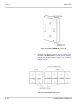
1. Refer to the template, and thread the included screw
into the wall at location for the top hole of the
DBM(B)-U( ) Box. Leave screw extended 1/8 inch.
Refer to Figure 7-35 Threading Screw into Wall.
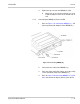
2. Place hole for mounting over the screw, and Hang
the DBM(B)-U10 on the screw. Refer to Figure 7-36
Hanging DBM(B)-U( ) on Screw.
Figure 7-35 Threading Screw into Wall