
Hardware manual


Issue 8 Electra Elite
5 - 140 Installing Electronic Telephone Units
7.6.5 Ethernet Status
Two Built-in LEDs (One green and one yellow) on the
front of each RJ-45 Connector indicate Ethernet
connection status. The yellow LED is On when the link is
up; the green LED is On to indicate activity.
7.6.6 Connectors
This ETU has the following connectors:
P1
Connects to the backboard
J1, J10, J11
Reserved for future use
J5
RJ-45 Ethernet connector for future use
J6
Default RJ-45 Ethernet connector
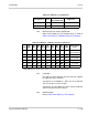
Table 5-64 IAD(8)-U( ) ETU Switches
Switch Setting Description
S1 Press to Reset Host Reset Switch
S2 Shown below Eight-position DIP Switch
S2-1~3 Always Off Reserved
S2-4 On (default) to enable
Off to disable
Auto Card Discovery Selection -
On only for first power on to
recognize ETU and set defaults
or for ESI(8)-U( ) ETU simulation
S2-5 Always On to enable 8
ports
(Off enables 4 ports)
Number of Voice Ports Selection
S2-6~8 S2-6 and S2-7 On for
DTI mode.
S2-6 On for ESI Mode
IAD(8)-U( ) ETU Mode
Selection to show simulated ETU