
Hardware manual


Electra Elite Issue 8
System Hardware Manual 5 - 95
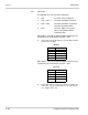
Refer toTable 5-39 CMS-U30 ETU LED Indications.
Table 5-39 CMS-U30 ETU LED Indications
LED Name Description
LED 1 APP1 Indicates status of voice mail application software
Green Application running without errors
Amber Application running with errors
Red Application not running
LED 2 APP 2 Not Used
LED 3 Drive HDD active light is red when the hard drive is accessed
Do not reset the ETU while this switch is on.
LED 4 CF Power On when shutdown switch in Run to indicate power on the ETU
LED 5 ICGA Live LED flashes every 125 ms during normal operation
LED 6 Shut Down
Switch
Indicates that the switch has no software control.
On red only when SHUTDOWN switch is in Run
LED 7 Shutdown On red when SHUTDOWN switch is in SHUT DOWN to
indicate that voice mail can be safely removed form the KSU
LED 8 Power On red when ETU is receiving power from the KSU
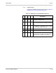
LED 9 FED DSP Used only for development purposes
LED 10 CH 1 On red when voice channel 1 is Off Hook
LED 11 CH 2 On red when voice channel 2 is Off Hook
LED 12 CH 3 On red when voice channel 3 is Off Hook
LED 13 CH 4
On red when voice channel 4 is Off Hook
LED 14 CH 5 On red when voice channel 5 is Off Hook
LED 15 CH 6 On red when voice channel 6 is Off Hook
LED 16 CH 7 On red when voice channel 7 is Off Hook
LED 17 CH 8 On red when voice channel 8 is Off Hook
The first four channel LEDs are also used during startup to show that the BICOM
driver is loaded (LED 1), Scan disk successfully completed (LED 2), CoSession Host
successfully Loaded (LED 3), and voice mail started successfully (LED 4). After the
system is up and running and all channels are ready to receive calls, these LEDs are
Off. When voice mail does not start successfully, all eight channel LEDs and LED 1
are On.