
Hardware manual


Electra Elite Issue 8
System Hardware Manual 5 - 63
4.12.2 Installation
When a PRT(1)-U( ) ETU is installed, a CLKG-U( ) Unit
must be installed on the CPUB( )-U10 ETU.
The PRT(1)-U( ) ETU (3 maximum) can be installed in
slots S1 and S4 of the basic B64-U10 KSU and Slot S1 of
the first expansion KSU in the system (S7000 or below).
Using S8000 or higher, a maximum of eight PRT(1)-U( )
ETUs can be installed in any interface slot in the system,
limited by 64 trunks.
4.12.3 Switch Settings
SW1, a 4-position DIP switch, assigns the application.
Refer to Table 5-23 PRT(1)-U( ) ETU SW1 Settings.
SW1-4 is not used and must be OFF.
Switch SW2 is an 8-position rotary switch that can be set
even during operation. A small flat screwdriver can be
used to set positions as follows:
Position 0 Alarm Indications
Position 1 B Channels 01~12 Status Indication
using LEDs 1~12
Position 2 B Channels 13~23 Status Indication
using LEDs 1~12
Positions 3 CO Trunks 01~12 assigned to PRT ETU
Status Indication using LEDs 1~12
Positions 4 CO Trunks 13~23 assigned to PRT ETU
Status Indication using LEDs 1~12
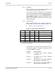
Table 5-23 PRT(1)-U( ) ETU SW1 Settings
SW1–1 SW1–2 SW1–3 SW1–4 Application
ON ON ON OFF NI-2
OFF ON ON OFF 4ESS (AT&T Custom)
OFF OFF ON OFF AT&T 5ESS (Lucent Custom)
ON ON OFF OFF DMS-100 (Custom) *
ON OFF ON OFF DMS-100 (National ISDN) **
* Nortel Specification NIS-A211-1
** Nortel Specification NIS-A233-1