
Hardware manual


Issue 8 Electra Elite
5 - 60 Installing Electronic Telephone Units
Ethernet Status
Two built-in LEDs (one green and one yellow) on
the RJ-45 indicate Ethernet connection status. The
yellow LED is On when the Ethernet link is up. The
green LED flashes to indicate activity.
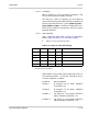
Status
This bi-color (red and green) LED shows status of
all Gateway trunks. When an error is detected, the
location is indicated by the following table.
4.11.4 IPT(4)-U( ) to IPT(8)-U( ) ETU Conversion
The IPE(4)-U( ) Unit is attached to the IPT(4)-U( ) ETU to
convert it to the IPT(8)-U( ) ETU. This unit comes with
two attached standoffs with an extra screw in the bottom.
1. Remove the screw from the bottom of each
standoff.
2. Line up the IPE(4)-U( ) Unit standoffs with Holes 1
and 2 and connector J1 with IPT(4)-U( ) ETU
connector J5, and press down until the IPE(4)-U( )
Unit is firmly attached to the IPT(4)-U( ) ETU.
3. Install the two previously removed screws through
holes 1 and 2 to Connect the standoffs to the
IPT(4)-U( ) ETU.
4.11.5 Connectors
The IPT(4)/(8)-U( ) ETU has two connectors:
CN1 Connects to the backboard
RJ-45 Connects to the Ethernet
Trunk Status LED Condition Error Location
Power On Off BIOS, Hardware
Start DSP download Red DSP Driver
DSP download OK Red and Green DSP Download
Successful Application
Start
Green Application Load