
Hardware manual


Electra Elite Issue 8
System Hardware Manual 5 - 37
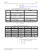
4.5.3 Switch Settings
Refer to Table 5-13 COIB(4)-U20/30 ETU Default Switch/
Jumper Settings.
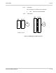
4.5.4 LED Indications
4.5.5 Connectors
The COIB(4)-U20/30 ETU has the following connectors:
CN1 Connects to the backboard
CN2 Future
CN3 Future
Table 5-13 COIB(4)-U20/30 ETU Default Switch/Jumper Settings
Switch/
Jumper
Setting Description
JP100~400 Jumpers 1-2 shorted 6dB increase
Jumpers 2-3 shorted (default) No Gain
Jumpers 3-4 shorted 6dB decrease
Receive pad for related channel.
JP101~401 Jumpers 1-2 shorted 6dB increase
Jumpers 2-3 shorted (default) No Gain
Jumpers 3-4 shorted 6dB decrease
Transmit pad for related channel.
S1 Open for COI
Shorted (default) for COID
Selects the function for COIB(4)-U20 ETU
between COI or COID mode
Reset N/A Resets the COIB(4)-U20 ETU
Table 5-14 COIB(4)-U20/U30 ETU LED Indications
LED Description On Flashing Off
LIVE ETU status Operation stopped
(Power On)
Normal Operation No Power
LED 1 Channel 1 status Busy Not Used Idle
LED 2 Channel 2 status Busy Not Used Idle
LED 3 Channel 3 status Busy Not Used Idle
LED 4 Channel 4 status Busy Not Used Idle
FAX FAX status Busy Not Used Idle