
Hardware manual


Electra Elite Issue 8
System Hardware Manual 5 - 27
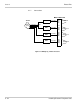
CN401 and CN402
Set the 100
termination to On or Off for Circuit 4.
Jumper Pins 1 and 2 are shorted together at the
factory to turn on the 100
terminal.
4.2.5 LED Indications
Refer to Table 5-8 BRT(4)-U20 LED Indications.
4.2.6 Connectors
The BRT(4)-U20 ETU has the following connectors:
CN1
Connects to the backboard
CN3
DB9 Pin Male connector used for maintenance
Table 5-8 BRT(4)-U20 LED Indications
LED Description On Flashing Off
LED 1 ETU status Operation
stopped
(Power On)
Normal
Operation
No Power
LED 2 L1 status - BRI
CKT1
L1 working Not Used L1 idle
LED 3 L1 status - BRI
CKT2
L1 working Not Used L1 idle
LED 4 L1 status - BRI
CKT3
L1 working Not Used L1 idle
LED 5 L1 status - BRI
CKT4
L1 working Not Used L1 idle
LED 6 B1 or B2 status
Circuit 1
Busy Not Used Idle
LED 7 B1 or B2 status
Circuit 2
Busy Not Used Idle
LED 8 B1 or B2 status
Circuit 3
Busy Not Used Idle
LED 9 B1 or B2 status
Circuit 4
Busy Not Used Idle