
Hardware manual


Electra Elite Issue 8
System Hardware Manual 4 - 7
Third ETU
42 YL–OR GN BK T T T T T T T GND TA* TA-1
EP
Zone 3
DP
1
ZT II
1
17 OR–YL RD YL R R R R R R R — TB* TB-1
43 YL–GN GN BK T T T T T T T E-1 RA* RA-1
EP
Zone 2
DP
2
18 GN–YL RD YL R R R R R R R M-1 RB* RB-1
44 YL–BR GN BK T T T — T T T T-1 — TA-2 EP
Zone 1
DP
3
ZT II
2
19 BR–YL RD YL R R R — R R R R-1 — TB-2
45 YL–SL GN BK T T T — T T T T1-1 — RA-2 Night
Chime
DP
4
20 SL–YL RD YL R R R — R R R R1-1 — RB-2
46 VI–BL GN Bk T T — — T — — GND — TA-3 External
Ringer
4
DLR
1
21 BL–VI RD YL R R — — R — — — —
TB-3
47 VI–OR GN BK T T — — T — — E-2 — RA-3 External
Ringer
3
DLR
222 OR–VI RD YL R R — — R — — M-2 —
RB-3
48 VI–GN GN BK T T — — T — — T-2 — TA-4 External
Ringer
2
DLR
3
23 GN–VI RD YL R R — — R — — R-2 —
TB-4
49 VI–BR GN BK T T — — T
Fax
Brnch
— T1-2 — RA-4 External
Tone
Ringer
1
DLR
4
24 BR–VI RD YL R R — — R — R1-2 —
RB-4
50 — — — ————— —————
25 — — — ————— —————
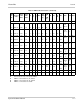
* Series 8000 or higher
PFT circuits are only connected to AMP3.
AMP1 is connected to S1, S2, and S3.
AMP2 is connected to S4, S5, and S6.
AMP3 is connected to S7 and S8.
Table 4-1 MDF Cable Connections (Continued)
MDF
Pin
N0.
Running
Cable
Station
Cable
DTU
Station
Cable
ETW
ESI
SLI
(8)
SLI
(4)
OPX
COI/
COID
(8)
COI
COIB
or
COID
(4)
DID TLI
DTI/
PRT
BRT ECR DPH BSU