
Data Sheet

103 mm
9 mm
29 mm
147 mm
36 mm
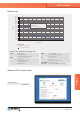
Enclosure opening
for DIP switch setup
DC UPS | UPSIC
RL
PBR –
PBR +
INOUT
RL
RS232
IN –
IGN
OUT +
OUT –
IN +
Drawing UPSIC-1205D
Tolerance ±0.5 mm
Bicker Elektronik GmbH | 86609 Donauwörth | Germany
Tel. +49 906 70595-0 | info@bicker.de | www.bicker.de
Connectors
RS232
01 DCD at PC – Detection cable connected
02 TXD (is connected to RXT at PC)
03 RXD (is connected to TXD at PC)
04 Shutdown signal detection
05 GND
06 DSR at PC – Detection caps loading status
07 RTS at PC – Supply voltage
08 CTS at PC – Power Fail detection
09 N/A
RL / PBR
04 / RL Relay connection
03 / RL Relay connection
02 / PBR – (V –) Shutdown-Signal (Impulse 200-400 ms)
01 / PBR + (V +) Shutdown-Signal (Impulse 200-400 ms)
IN / IGN / OUT
05 / IN + V + Input
04 / IN – V – Input
03 / N.C. N.C.
02 / OUT + V + Output
01 / OUT – V – Output
UPS systems
DC UPS
1
ON
23456
Specification is subject to change without notice. Errors excepted. Status as at: 04.02.2019
1
ON
23456
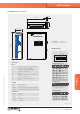
CAPS FULL
SD(RB)PF
DIP switch setup
Power Fail: relay contact 3+4 = 0 Ω
0.5 A @ 125 VAC / 1 A @ 24 VDC
1
ON
23456
CAPS FULL
SD(RB)PF
Shutdown Timer
PIN 2 1
No Reboot ON ON
Reboot after 10s OFF ON
Reboot after 30s ON OFF
Reboot after 60s OFF OFF
ON Output released
when V
CAP
over 90 %
Output release
PIN 3
Power Fail (PF) - Timer
6 5 4 PIN
ON ON ON Software
OFF ON ON 3s
ON OFF ON 8s
OFF OFF ON 20s
ON ON OFF 40s
OFF ON OFF 60s
ON OFF OFF 100s
OFF OFF OFF 150s