Installation Manual Volvo S60R Front Mount Intercooler System
Volvo S60R Intercooler System / Installation Manual C Contents Important Information 1 Parts List 1 Required Tools and Materials 2 1.0 Vehicle Preparation 2 2.0 Removing Front Fascia (Nose Section) 3 3.0 Removing Bumper Reinforcing Bar 4 4.0 Removing Air Filter Assembly 5 5.0 Removing Factory Intercoolers and Tubes 6 6.0 Drilling, Trimming and Misc. 9 7.0 Installing New Intercooler 10 8.0 Installing New Intercooler Tubes 12 9.
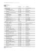
Volvo S60R Intercooler System / Installation Manual 1 Parts List Part Name Packet/Box Qty Part Number Intercooler Assembly Intercooler 1 A3001361806070(B) Intercooler Mounting Spacer Parts - Bag 1 2 PLV6070-12 M10-1.25 x 80mm Bolt - Hex Head Parts - Bag 1 2 P00700-M10-80-Z M10 Washer Parts - Bag 1 4 P00740-M10-C M10-1.
Volvo S60R Intercooler System / Installation Manual 2 Required Tools and Materials To effici supplied with your intercooler. Tools • 1/4” Drive Ratchet • 1/4” Drive Extensions - 3” and 6” Length • 3/8” Drive Ratchet • 3/8” Drive Extension - 3” Length • Sockets 8-17mm (1/4” or 3/8” Drive) • 11 mm Deep Socket • Wrench (Open/Boxed) 8-17mm • T-25 and T-15 Torx Bits • Flat-head Screwdriver • Phillips Screwdriver • Electric Handheld Drill (capable of holding .5” bit) • Drain Pan for Engine Coolant • .
Volvo S60R Intercooler System / Installation Manual 2.0 3 Removing Front Fascia (Nose Section) Note: Before beginning any work on the vehicle the battery must be disconnected. See page 1 for details. The first step in the installation will involve removal of the front nose section or fascia of the vehicle (Fig. 2.1). Attached to the front fascia are: the upper grill assembly, the front license plate and mounting bracket, the driving light assemblies and driving light grills.
Volvo S60R Intercooler System / Installation Manual 2.6 Remove Front Fascia Note: This process can be accomplished by a single person if you know what to expect and proceed carefully. That said, it is much easier and safer for the paint work if you have an assistant. • Grasping the rear edge of the front fascia (at the wheel opening), gently pull the fascia out, to the side, approximately .5”, to clear side clips, and move fascia forward about two inches. Repeat for other side.
Volvo S60R Intercooler System / Installation Manual • Using the .420” drill bit, enlarge each of the two mounting holes. The holes are only approximately .25” deep, only drill deep enough to properly enlarge the holes to prevent damage to radiator. • Remove mounting pins from each side. • Using the .312” drill bit, enlarge the mounting pin holes in both the bumper reinforcing bar and the radiator bulkhead. 3.
Volvo S60R Intercooler System / Installation Manual • The air filter box is now ready to be removed. Lift the front of the air filter box and remove air filter box from air inlet tube. Once clear of the air inlet tube, lift air filter box and disconnect vacuum line bundle, located on the driver’s side of the air filter box. This bundle of vacuum lines is secured to air filter box with a tab and it can pulled off. 6 Air Inlet Tube Hose Clamp Mass Air Sensor • Remove air filter box. Figure 4.2 5.
Volvo S60R Intercooler System / Installation Manual 7 5.4 Drain Engine Coolant Note: You may wish to replace your engine coolant and radiator hoses as part of routine maintenance. • Locate the plastic radiator drain plug/nozzle at the lower right (driver side) corner of the radiator (see Fig. 5.2). • Remove cap from coolant reservoir in engine compartment. • Position drain pan and loosen, but do not remove drain plug. Coolant will drain without the drain plug being completely removed.
Volvo S60R Intercooler System / Installation Manual 8 5.8 Reposition AC Dryer Note: This step may or may not be required for your particular vehicle. S60R model years 2004-2005 use a larger AC dryer canister than the later 20062007 models (see Fig. 5.5 and 5.6). If your vehicle is equipped with the smaller AC dryer canister you will not need to perform this step and should skip to Step 5.9. This step in the installation process requires repositioning the AC dryer (see Figure 5.
Volvo S60R Intercooler System / Installation Manual 6.0 9 Drilling, Trimming and Misc. 6.1 Installing Horn Brackets Installation of the larger intercooler requires the use of new horn brackets. These brackets rotate the horns from their original vertical position in the upper grill opening to a horizontal position (see Fig. 6.1). The following brackets and fasteners are provided with your intercooler system: New Components Horn Bracket - Left Horn Bracket - Right M6-1.0 x 20mm Bolt - Hex Head M6-1.
Volvo S60R Intercooler System / Installation Manual 10 • Radius each of the upper corners as shown in Figure 6.4b. A .5” radius is shown. Using a hacksaw or cutting tool, cut carefully along lines. Exercise care to avoid damaging the radiator. Smooth edges with flat and round files. Figure 6.4c shows the finished AC charging port opening shape. • Coat any exposed metal with touch-up paint.
Volvo S60R Intercooler System / Installation Manual 11 7.3 Reinstall Bumper Reinforcing Bar • Position bumper reinforcing bar and install using inner bumper spacers (one per side) and fasteners (see in Fig. 7.4). Do not tighten. If bolt does not align with hole you may need to adjust frame mounting tabs (see Fig. 7.3) Mounting Tabs • Position and install outer bumper spacers and fasteners as shown in figures 7.4 and 7.7. Do not tighten.
Volvo S60R Intercooler System / Installation Manual 8.0 12 Installing New Intercooler New Components AC Condenser / Radiator Spacer Intercooler M10-1.25 x 80mm Bolt - Hex Head Intercooler Spacer M10-1.25 Hex Nut (Mechanical Locknut) M10 Washer 8.1 Install New Intercooler The new Intercooler will be installed with the mounting brackets facing forward. When the Intercooler and Intercooler Spacers are installed properly there will be approximately a .
Volvo S60R Intercooler System / Installation Manual 13 The hose clamps for the intercooler inlet tube and intercooler outlet tube may positioned as shown in Figures 9.3a, 9.3b, 9.4a, 9.4b and 9.4c to allow for easy access for tightening while not rubbing on the front fascia bodywork. 9.1 Relocate Wiring Harness To avoid damage to wiring harness due to close proximity to accessory drive belt and pulley it is necessary to relocate a short portion of the wiring harness.
Volvo S60R Intercooler System / Installation Manual 14 • On vehicles with small AC dryer canister check for clearance issues with AC dryer line and carefully adjust line position as needed. • Carefully check for clearance issues with wiring harness and adjust as needed. If the harness is allowed to make contact with the engine accessory drive belt or pulley it will be damaged quickly and this damage can be expensive.
Volvo S60R Intercooler System / Installation Manual 15 9.5 Install Hoses and IAT Sensor • Reinstall vacuum/boost hose, attaching to hose boss on throttle inlet tube (see Fig. 9.5). Vacuum/Boost Hose • Using supplied bolt and washer, reinstall IAT sensor attaching to mounting boss on intercooler outlet tube as shown (see Fig. 9.5). • Reconnect IAT sensor wiring harness. 9.6 Recheck Clearances and Hose Clamps Before proceeding, recheck all tube clearances.
Volvo S60R Intercooler System / Installation Manual 16 • Remove car from jack stands or lift. • Reconnect battery. • Start engine and allow engine to warm to operating temperature. Watch temperature gauge closely and check for function of engine cooling fan. Shut off engine immediately if any gauges or engines lights indicate abnormal function. • Engine should idle and rev normally. If it does not, shut off engine and check for loose intercooler tubes/hoses and disconnected wiring harnesses.
Volvo S60R Intercooler System / Installation Manual 17 Trim Line 5/8” from Front Edge Discard Front Section Trim Line on Styrofoam Impact Strip Figure 12.2 Plastic Substructure Trim Line Detail Figure 12.3 Plastic Substructure After Trimming Figure 12.4 Bell Intercoolers, inc. © 2009 All rights reserved.
Volvo S60R Intercooler System / Installation Manual 18 Plastic Substructure Trim Line Detail Figure 12.5 Plastic Substructure After Trimming (also showing styrofoam impact strip after trimming) Figure 12.6 Plastic Substructure After Trimming Figure 12.7 Bell Intercoolers, inc. © 2009 All rights reserved.
Volvo S60R Intercooler System / Installation Manual 19 Plastic Substructure After Trimming Figure 12.8 Plastic Substructure and Styrofoam Impact Strip After Trimming Figure 12.9 Plastic Substructure After Trimming Figure 12.10 Bell Intercoolers, inc. © 2009 All rights reserved.
Volvo S60R Intercooler System / Installation Manual 13.0 ! 20 Trim and Install Front Fascia (Nose Section) This step requires relatively easy trimming of the plastic and urethane components of the front fascia and underbody tray. All trimming can be easily accomplished with a hacksaw or cutting wheel and cleaned up with a file and sand paper. You may also use a heated carpet knife to trim some of the urethane components (lower grill opening and driving light area).
Volvo S60R Intercooler System / Installation Manual 21 Cut Lines Figure 13.6a Figure 13.6b Figure 13.6c • Identify tab indicated in Figure 13.7. • Cut off tab and clean up cut edge with file and sandpaper. • Reinstall driving light insert into front fascia. 13.4 Trim Underbody Tray To provide space for the intercooler inlet tube it is necessary to trim a portion of the underbody tray in the area behind the left side (passenger side for US/Canada market cars) as shown in Figure 13.8a.
Volvo S60R Intercooler System / Installation Manual 14.0 22 Test Drive and System Checks Testing should be done with the radio and AC/heat fan off and with all windows rolled up to allow you to properly hear the engine. Allow engine to reach operating temperature and make certain the engine is running smoothly and normally, both at idle and under load, prior to applying boost.