Installation Manual Volvo S40 T5 Front Mount Intercooler System
Volvo S40 T5 Intercooler System / Installation Manual C i Contents Important Information i Parts List i Required Tools and Materials 1 1.0 - Vehicle Preparation 1 2.0 - Removing and Trimming Front Fascia (Nose Section) 2 3.0 - Removing Factory Intercoolers and Tubes 3 4.0 - Installing New Intercooler 4 5.0 - Start Engine and Check Connections 6 6.0 - Trim and Install Front Fascia (Nose Section) 7 7.
Volvo S40 T5 Intercooler System / Installation Manual 1 Required Tools and Materials To effici supplied with your intercooler. Tools • 1/4” Drive Ratchet • 1/4” Drive Extensions - 3” Length • 3/8” Drive Ratchet • 3/8” Drive Extension - 3” Length • Sockets 8 - 17 mm (1/4” or 3/8” Drive) • 11 mm Deep Socket • Wrenches (Open/Boxed) 8 - 17 mm • Straight Edge Ruler Materials • WD-40, Motor Oil or Lubricant 1.
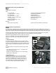
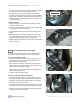
Volvo S40 T5 Intercooler System / Installation Manual 2.0 2 Removing Front Fascia (Nose Section) The first step in the installation will involve removal of the front fascia (front nose section) of the vehicle (see Fig. 2.1). Attached to the front fascia are the upper grill assembly, the front license plate and mounting bracket, the driving light assemblies and driving light grills, if so equipped.
Volvo S40 T5 Intercooler System / Installation Manual you feel a click, when the rivet has released. Once released, you may extract the rivet from the hole. Repeat for all rivets. • The lower portion of the front fascia/lower panel assembly is secured by three plastic tabs inserted into the metal lower radiator support. Using a screwdriver carefully release these tabs and pull the fascia assembly forward to disengage. The front fascia is now ready to be removed. 3 Upper Radiator Bulkhead 2.
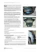
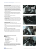
Volvo S40 T5 Intercooler System / Installation Manual 4 3.3 Remove Hose Clamps The factory hose clamps will be replaced with high-strength T-bolt hose clamps for use with your new intercooler. You will need to remove the factory hose clamps prior to installing the new intercooler. Mounting Bolt • Carefully remove factory hose clamps from intercooler inlet and outlet hoses. These clamps are secured by a small metal barb that grips the rubber hose. To release the barb carefully pry barb away from hose.
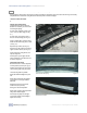
Volvo S40 T5 Intercooler System / Installation Manual 5 • Apply a thin coating of motor oil to the IAT sensor o-ring. • Carefully insert sensor into new intercooler. Position as shown in Figure 4.1. • Install M5- 0.8 x 20mm bolt and M5 washer (supplied with intercooler kit) to secure fastener. Tighten fastener. 4.2 Install T-Bolt Hose Clamps The T-Bolt hose clamps must be installed prior to installing the intercooler. Refer to Figures 4.2 and 4.
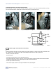
Volvo S40 T5 Intercooler System / Installation Manual 6 4.6 Recheck All Fasteners, Hose Clamps and Connections Before proceeding, recheck all hose clamps for proper installation and clearance. Also recheck intercooler position (as per step 4.3) and all mounting fasteners. Recheck IAT sensor harness to be sure it is properly connected. Intercooler Mounting Point Left-Side Mounting Point Figure 4.5 Intercooler Mounting Point Right-Side Mounting Point Intercooler To Radiator Gap Figure 4.4 Figure 4.
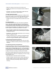
Volvo S40 T5 Intercooler System / Installation Manual 6.0 7 Trim and Install Front Fascia (Nose Section) This step requires relatively easy trimming of the plastic and urethane components of the front fascia. All trimming can be easily accomplished with a hacksaw or cutting wheel and cleaned up with a file and sand paper. 6.1 Remove Lower Grill Insert The 6.2 Mark Lower Grill Opening To provide adequate room for the new intercooler it is necessary to trim the back of the lower grill opening.
Volvo S40 T5 Intercooler System / Installation Manual 8 • Reinstall plastic rivets and fasteners across upper radiator bulkhead. • Reinstall headlight washer covers (if so equipped). • When installed, there should be a 1/8” - 1/4” gap between the intercooler surface and the back of the lower grill opening (see Fig. 6.3). 6.4 Reinstall Splash Guard Reinstall splash guard in reverse sequence of removal process (see Step 2.2, pg 2). • Reinstall and tighten seven (7) T30 Torx fasteners securing splash guard.