
User guide

6
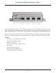
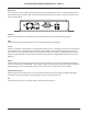
VOCIA PAGING STATION INTERFACE 1 (VPSI-1)
RS-232 or LED Conguration
The DB-9 connector can be congured one of two ways, LED mode, labeled as ‘Auxiliary Microphone’ mode in the software or RS-232
mode, labeled as ‘Remote Control’ mode in the software.
LED mode allows an external (customer supplied) LED circuit to display Paging indication status.
RS-232 mode allows a third party control system to control the host Paging Station using Vocia Text Protocol (VTP) messages.
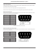
Wiring when using LED indicators:
When connected to a Paging Station or VI-6, the VPSI-1 DB-9 connector can used to facilitate connections to LED indicators. A custom
circuit will be required which must be wired as indicated below.
Note: LED outputs driven by 15mA current sinks.
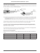
Wiring when using RS-232 Serial control for PS-VTP:
When connected to a Paging Station the VPSI-1 DB-9 connector can be used to facilitate connections to an external control system and
must be wired in the following manner.
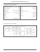
Pin Out Function
Pin 1 Busy LED
Pin 2 Host TXD
Pin 3 Host RXD
Pin 4 Talk LED
Pin 5 GND / 0V
Pin 6 TXD Link Back
Pin 7 RXD Link Back
Pin 8 Wait LED
Pin 9 12 Volt DC
Pin Out Function
Pin 2 RX from control system
Pin 3 TX from control system
Pin 5 GND
Do Not Wire Any Other Pins
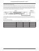
RS-232 Connection Settings
Baud Rate - 57600 bps Data Bits - 8
Parity - None Stop Bits - 1
Flow Control - None