
Datasheet

.10
2.54
.02
0.51
.10
2.54
.10
2.54
C
L
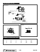
Schematic Diagram
This Surface
Model 64W
Model 64
1-30
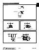
TOP ADJUSTMENT (Inch/mm)
.070 ± .005
1.78 ± 0.13
.020
0.51
.050
.040
1.02
1.27
.040
1.02
.020
0.51
.172
4.37
.270 ± .020
6.86 ± 0.51
Ø.018 ± .002
0.46 ± .05
.020
0.51
.165 ± .020
4.19 ± 0.51
.250 ± .020
6.35 ± .0.51
Metal Adjustment Screw
Dia. With Slot
Wide x
Standard Marking
On This Surface
Min.
Note: Model 64W dimensions applicable to all models except as noted
Min.
123
Terminal Pins (3)
Solderable
Min. Min. Deep
Model 64W and 64Y
.10
2.54
.092
2.34
.10
2.54
C
L
Model 64Y
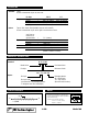
STANDARD RESISTANCE VALUES, OHMS
10 100 1K 10K 50K 250K
20 200 2K 20K 100K 500K
50 500 5K 25K 200K 1Meg