
User's Manual


Wireless Mini Analyser User Manual
Wireless Mini Analyser User Manual V1_06
1_04
16 of 32
RD096 071112
At power on the co-ordinator node (Wireless PC Module) enters pairing mode (fast flashing Link LED). In this mode
it listens for any programmed device that is in range.
When an end device node (Wireless Analyser Module) is powered on it also enters pairing mode (fast flashing Link
LED).
When a compatible co-ordinator node and end device node are operating in pairing mode are within range of
each other, a link will be established. When the devices pair the link status LED on both devices will change
from fast flashing to double blink to indicate this. Once established the link will remain valid until one or other
of the devices times out due to lack of data transfer activity on the radio link.
By default the co-ordinator node Link_timeout is 15s, whereas the end device Link_timeout is 10s. It is intentional
that the end device Link_timeout is shorter than that of the co-ordinator Link_timeout.
If the end device node fails for any reason, then the co-ordinator node will revert to pairing mode after its
Link_timeout expires. This will allow a new end device node that is in the co-ordinator’s allowed list to be accepted.
The link establishment strategy is fully fault tolerant, and will automatically handle power cycling of devices in any
order, and will automatically re-establish a link in the event of an end device failure. If the co-ordinator node is lost
through power failure, the link will automatically restart once power is re-applied.
6 Operation
Operation of the Wireless Mini Analyser falls into two parts, collection of the wheel sensor information using the Mini
Analyser itself, and gathering of the information stored in the Mini Analyser via the wireless link to the host PC.
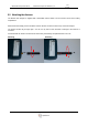
6.1 Wheel Assignment
The purpose of the Wireless Mini Analyser is to provide a convenient method for the assignment of wheel sensors to
their appropriate location on the car, should the normal automated process fail for any reason.
In order to position a sensor the operator should LF trigger the sensor via one of the Position Assignment Keys on
the analyser [FL] [FR] [RL] [RR]. When the sensor responds, and the Mini Analyser receives the RF datagram the
data is automatically assigned it to the appropriate corner based on the Position Assignment Key used to trigger the
sensor. When a sensor is positioned successfully a splash screen is displayed, together with a beep and flashing of
the Tx/Rx LED.
S
e
N
s
o
r
P
o
s
i
t
i
o
n
F
L
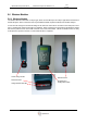
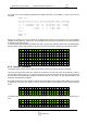
If an RF datagram is not received within 500ms in response to the LF trigger, then the Mini Analyser will
automatically reattempt to trigger the sensor again after a further 500ms (i.e.: 1s between LF trigger attempts). The
Mini Analyser will make up to 5 retries to LF trigger the sensor. If no RF datagram has been received after the fifth
retry, a splash screen will be displayed, accompanied by a beep and flashing of the Tx/Rx LED.
L
F
T
r
i
g
g
e
r
!
!
!
F
A
I
L
E
D
!
!
!