
User's Manual


bf1systems IRTPTMS V3 System Description
bf1systems IRTPTMS V3 System Description V1_01
1_01
Page 7 of 15
RD096 110124
7 System Components
The system components of the IRTPTMS are described in the following sections.
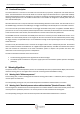
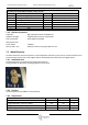
7.1 Motorsport DigiTyre ECU (MDE)
The MDE control unit consists of a printed circuit board with a microcontroller and interfaces for CAN, RS232 and TPMS-
LIN.
The tyre information received from the digital antennae is recorded and evaluated in the control unit. The pressure
information and, if applicable, the warning information, is forwarded via the CAN bus to the display systems in the
vehicle.
The information from the digital antennae is transferred to the control unit via a LIN bus communication link. The
control unit is the master here, while the antennae and/or the trigger transmitters work as slaves. The control unit
interrogates the digital antennae at set intervals with respect to radio messages. The trigger transmitters are contacted
in sequence. The control unit also provides the supply voltage to the trigger transmitters and the antennae. The most
important details of the control unit are described below.
7.1.1 Installation Area
The control unit is intended to be installed in the interior of the vehicle. If not stated otherwise, the values stated in the
following chapters relate to a temperature of 25°C and to the current sample control units based on the HCS12
processor.
7.1.2 Temperature Range
Operating temperature: -40°C to +80°C
Storage temperature: -40°C to +85°C
7.1.3 Voltage Range
Nominal voltage: 12V
Operating voltage: 9V to 16V
Maximum voltage: 0 to +18V, with polar protection
Under voltage switch off: The control unit is switched off when V
batt
< 7.5V
No. of Antennas / triggers that can be supplied: 6
7.1.4 Current Consumption
Normal operation: < 200 mA @ 12V (without antennae or trigger)
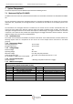
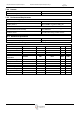
7.1.5 MDE Pin Description
System Connection (8STA2-10-35PN, Male, Circular)
Pin
Description
Pin
Description
1
Protected Ignition, +12 V
8
CAN L (DASH), BLUE
2
GND, LIN GND, RS232 GND
9
RS232 DATA TX / Configure Input A
3
LIN V RL TRIGGER Switched
10
RS232 DATA RX / Configure Input B
4
LINV TRIG FR/RR ANT FRT/REAR
11
LIN DATA RL TRIG/FRT ANT
5
LIN V FL TRIGGER Switched
12
LIN DATA FL TRIG/REAR ANT
6
LIN DATA FR TRIGGER
13
LIN DATA RR TRIGGER
7
CAN H (DASH), RED