
User's Manual


bf1systems IRTPTMS V3 System Description
bf1systems IRTPTMS V3 System Description V1_01
1_01
Page 12 of 15
RD096 110124
7.3.6 Environmental conditions
Protection class: IP 69K in line with test according to DIN 40050
Salt spray: 144h in line with test according to DIN 50021-SS
Pressure balance: Climate membrane 2 mm
7.3.7 LIN communication with MDE/Combined Antenna ECU control unit
The LIN communication of the antennas with the MDE/Combined Antenna ECU control unit fulfils the specification of
the LIN Consortium Version 1.1. The MDE control unit is in master operation here, while the antennas are in the slave
condition.
The following details apply:
LIN bit rate: 10k Baud +/-2%
LIN driver: Infineon TLE 6259-2G
Bus coupling: EMC network
Signal reference: Ground
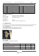
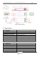
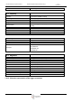
7.3.8 Connection occupancy, sleeve strip
Manufacturer: Tyco electronics AMP GmbH
Type, plug connector: MQS in line with Tyco drawing 114-18063-014
Contact system: Micro-Quad-Lock
Version: Pin shell
Number, contact pins: 4 Pins
Pin version: Sealed, gold-plated
(sealed; selectively gold-plated),
Sealing system: Primary sealing: Lamellar sealing in the housing
Secondary sealing: Individual seam sealing
Distance between pins (Pitch): 2.54x2.54mm
Pin:
Signal:
Description:
1
LIN_GND
LIN Ground
2
LIN_V1
LIN Supply voltage
3
LIN_DATA
LIN Data
4
SCREEN_GND
Ground for Screen Connection (optional)
Figure 2: Antenna pinout
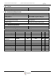
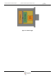
7.3.9 Block diagram
The basic electrical structure of the antenna electronics is outlined below.
Figure 3: RF Antenna structure
7.3.10 Assembly
The digital antenna can be mounted in the vehicle in line with the following sketch.