
User's Manual


bf1systems IRTPTMS V3 System Description
bf1systems IRTPTMS V3 System Description V1_01
1_01
Page 11 of 15
RD096 110124
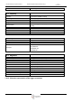
7.2.10 Transmission
Marking for type approval
433 MHz Version
Tolerance transmitted power
+/- 3 dB @ 25°C
Tolerance transmitted power over lifetime
- 3 dB
Tolerance transmitted power over working
temperature range
- 5 dB
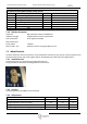
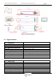
7.2.11 Block diagram wheel electronics
Figure 1: Wheel electronics block diagram
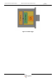
7.3 Digital antenna
The digital antenna has integrated signal conditioning (decoding processor) to receive and decode the HF signal sent by
the wheel electronics. The conditioned information is transferred to the MDE control unit via a LIN communication.
7.3.1 Installation area
The digital antennae are mounted on the outside of the vehicle. The area directly subject to being hit by stones from the
road must be avoided. The antennae should therefore be installed in a protected position behind a plastic trim (wheel
housing shell, or similar).
7.3.2 General dimensions and values
Dimensions: See Chapter on “Assembly”
Frequency range of the receiver: 550kHz @ -85dBm / 20°C
Type of modulations: FSK, hard keyed
Sensitivity within bandwidth @ 25°C >5nT <8nT
Reduction of Sensitivity over frequency max. 1nT
Reduction of Sensitivity over temp max. 1nT
Reception to wake-up: 5 dB +/-1dB
RSSI signal: Start of climb typically 16dBµV @ 25°C
Saturation typically 56dBµV @ 25°C
Radio data rate: 9.6kBaud +/- 10%
Radio reception frequency: 433.92 MHz +/-200kHz
7.3.3 Temperature ranges
Operating temperature: 0°C to + 125°C
Storage temperature: 0°C to + 70°C
7.3.4 Voltage supply
Supply line: Two wire circuit, V
batt
, GND
for each digital antenna
Supply voltage: > (V
batt
– 2V)
Switch type: High side switch
7.3.5 Current consumption
Supply current, digital antenna: At HF reception < 30mA permanently