3077860 BLAST CHILLER AND FREEZING CELLULES DE REFRIFERATION RAPIDE ET CELLULES MIXTES ABATEDORES DE TEMPERATURA USE AND INSTALLATION MANUAL MANUEL D’UTILISATION ET D’INSTALLATION MANUAL DE US Rev.
GB Carefully read the instructions contained in the handbook. You may find important safety instructions and recommendations for use and maintenance. Please retain the handbook for future reference. The Manufacturer is not liable for any changes to this handbook, which may be altered without prior notice. FR Lire avec attention les instructions contenues dans ce livret car elles fournissent d'importants renseignements pour ce qui concerne la sécurité, l'emploi et l'entretien.
- INDEX 1st PART INSTRUCTION MANUAL …………………………………3 2st PART INSTALLATION MANUAL ………………………………31 0 INFORMATION FOR THE READER ………………………………………………3 1 GENERAL INSTRUCTIONS ON DELIVERY ……………………………………3 • • • • • • GENERAL INSTRUCTIONS ……………………………………………………………………3 TECHNICAL DATA ………………………………………………………………………………3 LIST OF REGULATION REFERENCES ……………………………………………………3 GENERAL INSTRUCTIONS ……………………………………………………………………3 SETTING UP ………………………………………………………………………………………4 TESTING …………………………………………………………………………………………4 MACHINE LOADI
- INDEX • INSTALLATION …………………………………………………………………………………31 INTRODUCTION ……………………………………………………………………………………………………31 MAX ROOM TEMPERATURE ……………………………………………………………………………………31 POSITIONING ………………………………………………………………………………………………………31 WIRING ………………………………………………………………………………………………………………33 PLEASE USE CERTIFIED APPROVED MATERIALS …………………………………………………………33 REFRIGERATING CONNECTION …………………….
- INSTRUCTION MANUAL INFORMATION FOR THE READER This manual is subdivided into two parts. 1st part: covers all the information necessary to the user. CHAPTER 0 2nd part: covers all the information necessary to the qualified operators authorized to move, transport, install, service, repair and demolish the appliance. While users are instructed to refer to the 1st part only, the 2ndpart is addressed to skilled operators.
- INSTRUCTION MANUAL SETTING UP Before setting to operation thoroughly clean the cooling cabinet with a suitable detergent or sodium bycarb dissolved in lukewarm water. Clean the appliance inside to remove any condensate caused by the Manufacturer's final testing.
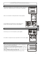
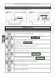
- INSTRUCTION MANUAL MACHINE LOADING Do not pile up foodstuffs to be cooled. Thickness should be lower than 2” in negative quick cooling and lower than 3” in positive quick cooling. (pict.1) Pict.1 Make sure air circulation is not hampered between food trays. (pict.2) 0.5 - 2 cm. 0,19”-0,79” Pict.2 The grid-holding frame (included in those models which include trolleys) is to be located at the centre of the cabinet. (pict.3) Pict.
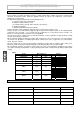
- INSTRUCTION MANUAL Table 3 shows the storing time rates for a few examples of frozen food. Do not leave cooked products at room temperature before quick cooling. Avoid any loss of moisture, which will affect food freshness. The cooled product should be wrapped in a specific film for foodstuffs (better still, vacuum stored) and provided with a sticker reporting the content [A], date of processing [B] and expiry date [C] written in permanent type ink (pict.6). Tab.
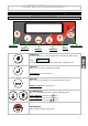
- INSTRUCTION MANUAL CONTROL PANEL CHAPTER 2 DESCRIPTION OF CONTROLS ON/OFF KEY START/STOP KEY ENTER KEY UP KEYS MENU KEY DOWN KEYS ON/OFF key Pressing the key for 5 sec the controller turns off and the sign blinks on the display OFF Pressing the key again the controller restarts in the Stand-By mode. Enter key Allows access to a menu or parameter selection. Manual defrost: press the key fro 5 s Menu key Allows access to the main menu or return to the previous menu.
- INSTRUCTION MANUAL CORE PROBE For proper position of the probe, refer to the following pictures.
- INSTRUCTION MANUAL CLOCK Press the menu key to select the desired menu Menu 06 Clock Setting Use the keys up and down to display Press enter to gain access to the clock setting mode The display shows Date: Hour: 06/11/05 14:22:46 Use the keys up and down to change the flashing digit Press enter to confirm and pass to the next value Press menu several times to exit TEMPERATURE UNIT OF MEASUREMENT Press the menu key to select the desired menu Use the keys up and down to display Menu 05 Set Up
- INSTRUCTION MANUAL Use the keys up and down to select the new value (0 Celsius, 1 Fahrenheit) Press enter to confirm your choice Press menu several times to exit 10
- INSTRUCTION MANUAL OPERATION CHAPTER 3 PRE-COOLING CYCLE We recommend starting a pre-cooling cycle before selecting quick cooling cycles.
- INSTRUCTION MANUAL TIME-CONTROLLED HARD QUICK COOLING CYCLE : cycle suitable for cooling foodstuffs with thickness exceeding 1,5” using a room temperature ranging from -22[°F] to +23[°F]. The cycle is time-controlled. NOTE: At the end of the quick cooling phase, the device starts the storing phase (+28[°F] at the end of the positive quick cooling; -7[°F] at the end of the negative quick cooling).
- INSTRUCTION MANUAL IFR POSITIVE QUICK COOLING CYCLE The IFR is an innovative patented system of positive quick cooling which allows the cycle optimisation for each type of foodstuffs by preventing superficial freezing. Temperatures are detected by a three-sensor multipoint needle probe. The position inside the foodstuff is determined univocally by a reference disk located along the needle. (ref. pag 8, par. “core probe”).
- INSTRUCTION MANUAL CORE PROBE POSITIVE QUICK COOLING CYCLE Press the menu key to select the desired menu Use the keys up and down to display Menu 01 Set Press enter to gain access to the mode for setting quick cooling cycles The display shows Quick Cooling Negative Press enter to change the flashing values Use the keys up and down to display Quick Cooling Positive Press enter to confirm your choice, the value stops flashing Use the keys up and down to pass to the next values The display shows Qu
- INSTRUCTION MANUAL Press enter to change the flashing values Use the keys up and down to display the desired value Press enter to confirm your choice, the value stops flashing Press the key start/stop to start the selected quick cooling cycle immediately CORE PROBE NEGATIVE QUICK COOLING CYCLE Press the menu key to select the desired menu Use the keys up and down to display Menu 01 Set Press enter to gain access to the mode for setting quick cooling cycles The display shows Quick Cooling Negative
- INSTRUCTION MANUAL Use the keys up and down to pass to the next values The display shows Speed 50% Press enter to change the flashing values Use the keys up and down to display the desired value Press enter to confirm your choice, the value stops flashing Press the key start/stop to start the selected quick cooling cycle immediately TIME-CONTROLLED POSITIVE QUICK COOLING CYCLE Press the menu key to select the desired menu Use the keys up and down to display Menu 01 Set Press enter to gain access
- INSTRUCTION MANUAL Press enter to change the flashing values Use the keys up and down to display the desired value Press enter to confirm your choice, the value stops flashing Use the keys up and down to pass to the next values The display shows Speed 50% Press enter to change the flashing values Use the keys up and down to display the desired value Press enter to confirm your choice, the value stops flashing Press the key start/stop to start the selected quick cooling cycle immediately TIME-CONTR
- INSTRUCTION MANUAL Press enter to change the flashing values Use the keys up and down to display the desired value Press enter to confirm your choice, the value stops flashing Use the keys up and down to pass to the next values The display shows Speed 50% Press enter to change the flashing values Use the keys up and down to display the desired value Press enter to confirm your choice, the value stops flashing Press the key start/stop to start the selected quick cooling cycle immediately CORE PROBE
- INSTRUCTION MANUAL Press enter to change the flashing values Use the keys up and down to display Quick Cooling Core Press enter to confirm your choice, the value stops flashing Use the keys up and down to pass to the next values The display shows Set Point -25 Press enter to change the flashing values Use the keys up and down to display the desired value Press enter to confirm your choice, the value stops flashing Use the keys up and down to pass to the next values The display shows Speed 50% Pre
- INSTRUCTION MANUAL Press enter to change the flashing values Use the keys up and down to display Quick Cooling Hard Press enter to confirm your choice, the value stops flashing Use the keys up and down to pass to the next values The display shows Quick Cooling Time Press enter to change the flashing values Press enter to confirm your choice, the value stops flashing Use the keys up and down to pass to the next values The display shows Length 90 min Press enter to change the flashing values Use th
- INSTRUCTION MANUAL STORING CYCLE Storing cycles and quick cooling cycles can be started separately POSITIVE STORING CYCLE Press the menu key to select the desired menu Use the keys up and down to display Menu 02 Storing Press enter to gain access to the mode for starting a storing cycle The display shows Storing Negative Press enter to change the flashing values Use the keys up and down to display Storing Positive Press enter to confirm your choice, the value stops flashing Use the keys up and do
- INSTRUCTION MANUAL Press the key start/stop to start the storing cycle immediately NEGATIVE STORING CYCLE Press the menu key to select the desired menu Use the keys up and down to display Menu 02 Storing Press enter to gain access to the mode for starting a storing cycle The display shows Storing Negative Press enter to change the flashing values Press enter to confirm your choice, the value stops flashing Use the keys up and down to pass to the next values The display shows Set Point -22 Press
- INSTRUCTION MANUAL MEMORIZING PROGRAMMES It is possible to memorize up to 20 USER programmes.
- INSTRUCTION MANUAL USING RECOMMENDED PROGRAMMES PRESET programmes are working cycles recommended by the manufacturer. Parameters cannot be changed.
- INSTRUCTION MANUAL Press enter to gain access to the defrost activation The display shows Start Defrost? No Ok Press Up to start defrost Press the key start/stop to stop defrost.
- INSTRUCTION MANUAL ACCESSORIES CHAPTER 4 The following accessories are available upon request. (pict.7) A A) THERMAL PRINTER B) PROBE SUPPORT (useful in quick cooling cycles for liquid foodstuffs) B Pict.7 PRINTING MEMORIZED CYCLES NOTE: the printer is not supplied as standard equipment. It is an optional item.
- INSTRUCTION MANUAL MAINTENANCE CHAPTER 5 MAINTENANCE AND CLEANING Clean inside the cooling cabinet daily. Both the cabinet and all the internal components have been designed and shaped to allow washing and cleaning all parts easily. Before cleaning, defrost the appliance and remove the internal drain. Disconnect the master switch. Clean all components (stainless-stell, plastic or painted parts) with lukewarm water and detergent. Then rinse and dry without using abrasives or chermical solvents. (pict.
- INSTRUCTION MANUAL Wash the door gasket with water. Accurately dry with a dry cloth. We recommend wearing protecting gloves throughout the operations. (pict.13) Pict.13 Hand-wash the probe using lukewarm water and a mild detergent or products with biodegradability higher than 90%. Rinse with water and sanitary solution. Do not use detergents containing solvents (such as trichloroethylene, etc) or abrasive powders ATTENTION: do not use hot water to wash the probe (pict.14) Pict.
- INSTRUCTION MANUAL DISCONTINUED USE Should the machine be disconnected over long periods, follow the instructions below to maintain the appliance in good condition: Turn the mains switch OFF. (pict.18) Pict.18 OFF Pict.19 Disconnect the plug. (pict.19) Empty the appliance and clean it in accordance with the instructions given in the chapter "CLEANING". Leave the door ajar to prevent a bad smell. Cover the compressor unit with a nylon cloth to protect it from dust. (pict.20) Pict.
- INSTALLATION MANUAL INSTALLATION INTRODUCTION After unpacking the appliance make sure it has not been damaged. (pict.21) Make sure the technical wiring specifications comply with the ratings (i.e., V, kW, Hz, no. phases and mains power Check the power supply type, adjustments, performance and calibration of the device located before the appliance. Check and record the coolant type inside the system and refer to the recorded data in any refill. Pict.
- INSTALLATION MANUAL Pict.25 Do not place the refrigerated compartment near heat sources. (pict.25) Pict.26 Remove pvc protective film from all over the appliance. (pict.26) Place the appliance onto the required working site. (pict.27) Pict.27 Pict.28 Avoid locations with exposure to direct sunlight. Do not place the appliance in hot, poorly-ventilated rooms. Leave a min. 4” clearance around the appliance on the sides where air inlet and outlet are located. (pict.
- INSTALLATION MANUAL WIRING The connection to power supply may be carried out at the back of the appliance after removing the protection grid. (pict.31) For remote condensing unit, to make the connection using: Multipolar wiring made by 11 poles with 4 section AWG 16 and 7 section AWG 12. Pict.31 PLEASE USE CERTIFIED APPROVED MATERIALS All wiring cables are to comply with the ratings shown on the technical specifications. Pict.34 Cables are to be connected to the equipotential terminal. (pict.
- INSTALLATION MANUAL GENERAL SETTING TESTING Carry out the following checkings: 1) Outside temperatures must be included between 50[°F] and 110[°F]. 2) Check power input. 3) Carry out at least one full quick cooling cycle Should the appliance have been transported horizontally instead of a vertical position DO NOT START THE APPLIANCE IMMEDIATELY. WAIT FOR AT LEAST 4 HOURS BEFORE OPERATING.
- INSTALLATION MANUAL CLOCK Press the menu key to select the desired menu Use the keys up and down to display Menu 06 Clock Setting Press enter to gain access to the clock setting mode The display shows Date: Hour: 06/11/05 14:22:46 Use the keys up and down to change the flashing digit Press enter to confirm and pass to the next value Press menu several times to exit TEMPERATURE UNIT OF MEASUREMENT Press the menu key to select the desired menu Use the keys up and down to display Menu 05 Set Up
- INSTALLATION MANUAL Press enter to confirm your choice Use the keys up and down to select the new value (0 Celsius, 1 Fahrenheit) Press enter to confirm your choice Press menu several times to exit PRINTER INSTALLATION The printer is not supplied as standard equipment . Should you purchase the printer, please follow the installation instructions to install.
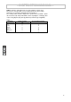
- INSTALLATION MANUAL Use the keys up e down to select the new value of the parameter Press enter to confirm your choice Press menu several times to exit DESCRIPTION OF PARAMETERS Parameter P01 P02 P03 P04 P05 P06 P07 N01 N02 N03 N04 A01 A02 A03 A04 A05 A06 A07 A08 D01 D02 D03 S01 S02 S03 S04 S05 S06 S07 S08 S09 Description POSITIVE QUICK COOLING Room SetPoint in pos. quick cooling, Soft phase SetPoint cella in abbattimento Hard Needle SetPoint in pos.
- INSTALLATION MANUAL Parameter S10 C01 C02 C03 C04 C05 C06 C07 C08 C09 C10 C11 C12 R01 R02 R03 R04 R05 R06 R07 R08 R09 R10 R11 R12 F01 F02 F03 F04 F05 F06 F07 F08 F09 F10 F11 PR1 Description Defrost type started through keyboard: 0= electrical or due to compressor stop 1= hot gas 2= air CONFIGURATION Door input (0 de-activated; 1 activated) Door open polarity Door open alarm delay Activates buzzer (0 de-activated; 1 activated) Buzzer duration at the end of quick cooling cycle Temperature difference in
- INSTALLATION MANUAL Parameter CF1 CF2 B01 B02 B03 B04 B05 B06 B07 B09 B10 B11 B12 B13 B16 B17 B18 B19 B20 B21 B22 B23 B24 B26 B27 B28 ADD SC MB1 MB2 G01 Description Default (IM...) VENTILATION SPEED (P.W.M.) Evaporator fan min. speed 20 Evaporator fan min. speed selectable in a quick cooling cycle 50 I.F.R.
- INSTALLATION MANUAL ALARMS AND FAULT ANALYSIS (TAB.5) Press the menu key to select the desired menu Use the keys up and down to display Menu 08 Alarm Press enter to gain access to the mode for displaying alarms No Date If there are no alarms memorized, the display shows If there are alarms memorized, the display shows the last alarm starting time as well as the progressive number ranging from A01 to A30 A05 Err Room S 14:21 15/12/03 Press enter to get further information about the alarm: The max.
- INSTALLATION MANUAL TAB.
- INSTALLATION MANUAL DISPLAYING THE LATEST DEFROST CYCLES Press the menu key to select the desired menu Use the keys up and down to display Menu 05 Set Up Press the enter key to gain access to the setting submenus The display shows Set Up Password 0 Use the keys up and down to select the password “-19” Press enter to confirm your choice Use the keys up and down to display Set Up 01 Defrost Press enter to gain access to the mode for displaying the latest 32 defrost cycles No Date If there are no
- INSTALLATION MANUAL Use the keys up and down to select the password “-19” Press enter to confirm your choice Use the keys up and down to display Set Up 02 Door Open Press enter to gain access to the mode for displaying the door opening records during a quick cooling of the last day. The controller allows to record up to 31 days.
- INSTALLATION MANUAL Press Up to cancel the whole memory Press menu several times to exit RESTORING PRE-SET PARAMETERS ATTENTION: should you use the device with the “RESTORE” option, available on the card, please apply to the manufacturer for proper setting of the electronic controller configuration parameters.
- INSTALLATION MANUAL MAINTENANCE OF PANEL BOARD The following operations are to be carried out by skilled staff only. Turn the mains switch OFF. (pict.38) Pict.38 OFF Pict.39 Disconnect the plug. (pict.39) To be able to access the electric picture: Pict.40 Mod. 22lb Remove the front panel (pict.40) with a tool and move the electric board box (pict.41) along the slides Pict.41 Remove the electrical board cover with a tool to access the internal components.
- INSTALLATION MANUAL Pict.45 Two delayed fuses are inserted in the power supply line; extract the blown fuse and replace it with a fuse having the same characteristics. (pict.45) WIRING DIAGRAM PLATE The diagram is shown on pict.47.
- INSTALLATION MANUAL REFRIGERANT MATERIAL SAFETY DATA SHEET R134a GWP = 1300 ODP = 0 R404a: fluid components trifluoroethane (HFC 143a) pentafluoroethane (HFC 125) tetrafluoroethane (HFC 134a) 52% 44% 4% GWP = 3750 ODP = 0 Hazard identification Overexposure through inhalation may cause anaesthetic effects. Acute overexposure may cause cardiac rhythm disorders and sudden death. Product mists or sprays may cause ice burns of eyes and skin.
- INSTALLATION MANUAL DIMENSIONS Please refer to the dimensions of your own appliance.
- INSTALLATION MANUAL ANNEXES TAB.
- INSTALLATION MANUAL TAB.
- INSTALLATION MANUAL Pict.47 N° DESCRIPTION N° DESCRIPTION 1 2 2A 3 3A 9 9A 20 44 COMPRESSOR CONDENSER FAN MOTOR CONDENSER FAN MOTOR TERMOST.