
Operating instructions


4
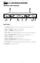
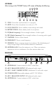
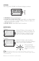
LCD PANEL:
After turning on the “POWER” button, LCD screen will display the following:
11. SYNC: Shows that synchronization is in progress.
12. MUTE: Shows that microphone is not set up or Off.
13. LOCK/UNLOCK: Shows whether current settings are locked.
14. BATTERY STATUS: Shows battery level of microphone.
15. RF (Radio Frequency): Shows strength indicator of radio signal.
16. DEV (Audio Frequency): Shows strength indicator of incoming audio signal.
17. CHANNEL: Shows current channel.
18. FREQUENCY: Shows current frequency.
19. SQUELCH: Shows coverage range of microphone. The disadvantage of
using a longer range is the increased chance of interference.
20. ANTENNA A/B: Shows the antenna in use. When one antenna
experiences noise or interference, the other antenna takes over.
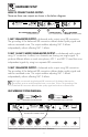
REAR PANEL:
21. ANTENNA-B: Connect antenna to BNC socket here.
22. MIC 2 BALANCED OUTPUT: XLR balanced audio output.
23. MIC 1 & MIC 2 MIXED OUTPUT: Unbalanced ¼ inch audio output.
24. POWER SUPPLY: Removable adapter with DC 12V 600mA.
25. MIC 1 BALANCED OUTPUT: XLR balanced audio output.
26. ANTENNA-A: Connect antenna to BNC socket here.
PEAK µV
100
60
25
5
RF
FREQUENCY SYNC MUTE
CH:
01
SQ:
6
PEAK %
100
60
25
5
DEV
835.500
MHz
GHz
ANT
A
ANT
B
15 16 17 18 19 20
11 12 13 14
XL R B ALAN CED
AUDI O OU TP UT
MIC 1
AN TEN NA-B AN TEN NA-A
DC 12V
/
600 mA
DC -PO WE R
362111109800
G3 SER IES
Gen eration 3
RISK OF ELECTRIC SHOC K
DO NOT OPEN
Taking apart or mo difying the
receive r may lead to elec tric shock,
fire, or dama ge to the recei ver and
will void yo ur warranty.
Mod el No.: V M-82U G3
(UHF Microp hone)
CALIFORNIA , UNITED STATES OF AMERICA
E-MAIL: sa les@better musicbuilder.c om
w ww .Be t te rM us icB ui ld er .c om
ENGINEERED AND DESIG N IN U.S.A.
SERIAL NO.
Bette r Music B uilde r
®
®
XL R B ALAN CED
AUDI O OU TP UT
MIC 2
MI XE D OU TP UT
MIC 1 & 2
¼” U NBAL ANCED
MIC 1 + MIC 2
21 262322 2524