
Operating instructions

4
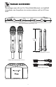
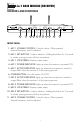
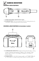
LCD PANEL:
After turning on the “POWER” button, LCD screen will display the following:
12. VOLUME: Displays the current microphone volume.
13. RADIO FREQUENCY: Strength indicator of radio signal.
14. CHANNEL: Displays the current channel.
15. FREQUENCY: Displays the current frequency.
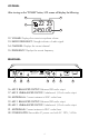
REAR PANEL:
16. MIC 2 BALANCED OUTPUT: Balanced XLR audio output.
17. MIC 2 UNBALANCED OUTPUT: Unbalanced 1/4 inch audio output.
18. ANTENNA-A: Connect antenna to BNC socket here.
19. MIC 1 BALANCED OUTPUT: Balanced XLR audio output.
20. MIC 1 UNBALANCED OUTPUT: Unbalanced 1/4 inch audio output.
21. ANTENNA-B: Connect antenna to BNC socket here.
22. POWER SUPPLY: Removable AC power cord with AC 120V / 60Hz.
2450.00
MHz
25
CHVOL
22
13
12
15
14
ANTE NNA-A ANTE NNA-B
RISK OF ELECTRIC SHOC K
DO NOT OPEN
Taking apart or mo difying th e
receive r may lead to elec tric shock,
fire, or dama ge to the recei ver and
will void yo ur warranty.
AC-PO WER
120V / 60Hz
Mod el No.: V M-93C G2
(UHF Microp hone)
CALIFORNIA , UNITED STATES OF AMERICA
E-MAIL: s ales@bette rmusicbuilde r.com
w ww .B et te rM us ic Bui ld er .c om
ENGINEERED AND DES IGN IN U.S.A.
SERIAL NO.
Bette r Musi c Buil der
®
®
360110810500
G2 SERIES
Generati on 2
¼” UNBAL ANCEDXLR B ALANCE D
MICR OPHONE 2 AUD IO OUT
¼” UNBAL ANCEDXLR B ALANCE D
MICR OPHONE 1 AUD IO OUT
16 17 18 19 2220 21