
Operating instructions

RISK OF ELECTRIC SHOCK
DO NOT OPEN
Taking apart or modifying the
receiver may lead to electric shock,
fire, or damage to the receiver and
will void your warranty.
UNBALANCED
A & B
MIX OUTPUT DC-POWER
DC 13~15V 600mA
Channel AChannel B
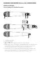
Model No. VM-92U (UHF Microphone)
CALIFORNIA, UNITED STATES OF AMERICA
COMMENTS? E-MAIL: info@bettermusicbuilder.com
www.BetterMusicBuilder.com
ENGINEERED AND DESIGN IN U.S.A.
FCC: 74.861
SERIAL NO.
AC POWER
AC~120V 60Hz 35W
CAUTION
0
36 1 20 0 6 09 0 8- 2 2
3
Better Music Builder
®
TM
UHF 32 CHANNEL SELECTABLE DIGITAL LCD DISPLAY
POWERANTENNA-A ANTENNA-B
AF RF
CH04:807.10 mh
z
UP
SET
SET
DOWN
MAXMIN
AF RF
CH24:813.10 mh
z
UP
SET
SET
DOWN
MAXMIN
VM-92U
Channel A Volume Channel B Volume
Better Music Builder
®
TM
21 4 93 5 8 1076
1312 14 15 16
3
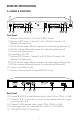
RECEIVER SPECIFICATION
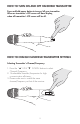
A. NAMES & FUNCTION:
Front Panel:
1. Receiver Antenna Input-A. (Channel A) BNC Socket.
2. Receiver A LCD screen: Channel A with 16 Built-In Channels with
different UHF frequencies.
3. DOWN button selects different frequency & model settings (Receiver A)
4. UP button selects different frequency & model settings (Receiver A)
5. Volume control (Receiver A)
6. Power button On/Off.
7. Receiver B LCD screen: Channel A with 16 Built-In Channels with
different UHF frequencies.
8. DOWN button selects different frequency & model settings (Receiver B)
9. UP button selects different frequency & model settings (Receiver B)
10. Volume control (Receiver B)
11. Receiver Antenna Input-B. (Channel B) BNC Socket.
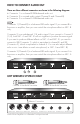
Rear Panel:
12. Channel B XLR 3M socket balanced audio output 50Hz~15kHz +/-3dB.
13. Channel A & B 1/4-inch (6.3 mm) jack socket unbalanced audio output,
mixed channel A & B.
14. Channel A XLR balanced audio output 50Hz~15kHz +/-3dB.
15. Power supply dock with removable IEC cable 13~15V 600mA.
16. 120V 60Hz 35W AC-Power Plug.