
Operating instructions
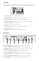
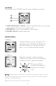

LCD PANEL:
After turning on the “POWER” button, LCD screen will display the following:
7. Antenna A/B: Displays the antenna in use.
8. Radio Frequency: Strength indicator of radio signal.
9. Audio Frequency: Strength indicator of incoming audio signal.
10. Channel & Select: Displays current channel & Selector for channel.
11. Frequency Select: Selects frequency.
12. Scan: Scans for microphone frequency.
13. Infrared Scan: Scans for microphone Infrared frequency.
14. Frequency: Displays current frequency.
15. Battery Status: Displays microphone battery status.
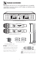
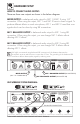
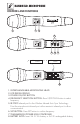
REAR PANEL:
16. ANTENNA-B: Connect the antennas to the BNC socket.
17. MIC 2 SQUELCH CONTROL: Distance coverage adjustment.
18. MIXED OUTPUT: unbalanced 1/4" audio output for MIC 1 & MIC 2.
19. MIC 2 BALANCED OUTPUT: balanced XLR audio output.
20. MIC 1 BALANCED OUTPUT: balanced XLR audio output.
21. POWER SUPPLY: Removable adapter with DC14~22V 500mA.
22. MIC 1 SQUELCH CONTROL: Distance coverage adjustment.
23. ANTENNA-A: Connect the antennas to the BNC socket.
ANTENNA -B ANTENNA -AMIC 2 SQUEL CH
MA X MIN MA X MIN
MIC 1 SQUEL CH
DC 14V
DC-POWER
MIC 2 BALANCED MIC 1 BALANCED
TRUE DIVERSITY
MIX
MIC 1 & 2
UNBAL AN CED
AU D I O OUTPU T
364130911000
Model No.: VM-92U G2
CALIFORNIA, UNITED STATES OF AMERIC A
w w w. Be tt e r Mu si cB u il de r . c om
ENGINEERED AND DESIGN IN U.S.A.
Better Music Builder
®
®
16 17 18 19 20 21 22 23
4
AF
CH IRFRQ SCAN
RF
B
750.000
MHZ
BAT
151413121110987