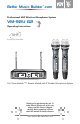
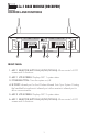
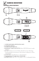
Better Music Builder .com ® Passionate about Music Professional UHF Wireless Microphone System VM-92U G2 110421 Operating Instructions UHF Frequency Selectable ON/OFF ON/OFF UHF WIRELESS SYSTEM VM-92U G2 MHz DUAL CHANNEL RECEIVER MIC 1 DOWN UHF 2-IN-1 BASE RECEIVER MODULE VM-92U G2 UP 725.000 B SET RF AF MHZ CH FRQ SCAN IR B BAT RF AF MHz MIC 2 UP 750.000 iR 5mW 750.00 UHF WIRELESS SYSTEM VM-92U G2 5mW 725.
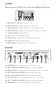
CONTENTS INTRODUCTION................................................................................ 1 Intro SYSTEM FEATURES............................................................................. 1 Features Package Base Module hand-held Operation PACKAGE ACCESSORIES................................................................... 2 2-in-1 BASE MODULE........................................................................ 3 • Controls and Functions..............................................
INTRODUCTION Intro Better Music Builder VM-92U G2 is a second generation wireless microphone that uses the latest UHF wireless technology. It is a heavy duty design which includes two hand-held microphones with one 2-in-1 Base Module, built-in LCD panel on both microphones and base units, solid built aluminum alloy handles, and Wireless Infrared Auto Sync System.
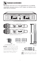
PACKAGE ACCESSORIES Package The package comes with one 2-in-1 Base Module [Receiver], two handheld microphones, two receiver antennas, one DC adaptor, one unbalance audio cable, and four AA batteries. DUAL CHANNEL RECEIVER MIC 1 A SET DOWN 2-IN-1 BASE RECEIVER MODULE UHF VM-92U G2 UP RF AF MHZ 750.000 CH FRQ SCAN IR B iR BAT RF AF 750.000 CH FRQ SCAN IR MIC 2 UP MHZ SET BAT DOWN POWER ON/OFF ON/OFF UHF WIRELESS SYSTEM VM-92U G2 5mW MHz 5mW MHz 725.
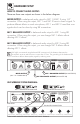
Base Module 2-in-1 BASE MODULE [RECEIVER] CONTROLS AND FUNCTIONS DUAL CHANNEL RECEIVER MIC 1 2-IN-1 BASE RECEIVER MODULE UHF MIC 2 VM-92U G2 UP A SET RF DOWN AF MHZ 750.000 CH FRQ SCAN IR B iR BAT RF AF UP MHZ 750.000 CH FRQ SCAN IR SET BAT DOWN POWER 1 2 3 4 5 6 FRONT PANEL: 1. MIC 1 SELECTOR BUTTONS (UP/SET/DOWN): Allows control of LCD screen and it’s functions 2. MIC 1 LCD SCREEN: Displays MIC 1 system status. 3. POWER BUTTON: Turns the system on/off. 4.
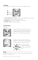
LCD PANEL: After turning on the “POWER” button, LCD screen will display the following: B 7 RF AF 8 9 MHZ 750.000 CH FRQ SCAN IR 10 11 BAT 12 13 14 15 7. Antenna A/B: Displays the antenna in use. 8. Radio Frequency: Strength indicator of radio signal. 9. Audio Frequency: Strength indicator of incoming audio signal. 10. Channel & Select: Displays current channel & Selector for channel. 11. Frequency Select: Selects frequency. 12. Scan: Scans for microphone frequency. 13.
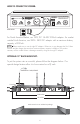
HARDWARE SETUP Set Up HOW TO CONNECT AUDIO OUTPUT: There are three rear outputs as shown in the below diagram: MIXED OUTPUT is unbalanced audio output for MIC 1 & MIC 2 using 1/4” connection. When using this output, MIC 1 and MIC 2 have to share a signal. To produce different effects on each microphone, MIC 1 and MIC 2 need their own signals which can be done by using XLR connections. MIC 1 BALANCED OUTPUT is balanced audio output for MIC 1 using XLR connection.
HOW TO CONNECT DC-POWER: MIC 2 BALANCED AUDIO OUTPUT ® Better Music Builder® MAX MIN MIC 2 SQUELCH ANTENNA-B MIC 1 BALANCED Model No.: VM-92U G2 364130911000 TRUE DIVERSITY MIX DC-POWER MIC 1 & 2 UNBALANCED DC 14V CALIFORNIA, UNITED STATES OF AMERICA w w w . B e t t e r M u s i c B u i l d e r. c o m ENGINEERED AND DESIGN IN U.S.A. MAX MIN MIC 1 SQUELCH ANTENNA-A REAR VIEW For North America Market, use 120V, DC 14~22V 500mA adaptor.
HANDHELD MICROPHONE Hand-held ON/OFF 2 3 5mW MHz 725.00 CONTROLS AND FUNCTIONS 1 UHF WIRELESS SYSTEM VM-92U G2 MHz 725.00 5mW AA 6 7 ALKALINE BATTERY ON/OFF ALKALINE BATTERY LEVEL L 5 AA H iR SET MHz 5mW ON/OFF 725.00 4 8 1. INTERCHANGEABLE MICROPHONE HEAD 2. LCD DIGITAL DISPLAY 3. POWER ON/OFF BUTTON 4. FREQUENCY SELECTION BUTTON: Press UP/DOWN button to select frequency. 5. IR PORT: Infrared port for the Wireless Infrared Auto Sync Technology.
LCD PANEL: After turning on the “POWER”, the LCD screen will light up as below: 5mW 1 10mW 725.00 2 MHz 3 1. RADIO FREQUENCY SIGNAL: Switch to High (10mW) to use a stronger signal and Low (5mW) to use a weaker signal. 2. FREQUENCY: Current value depends on your setting. 3. BATTERY STATUS: Indicates battery life. BATTERY STATUS: Full Battery 5mW 10mW 725.00 MHz Indicates full battery on the microphone.
OPERATION Operation HOW TO SELECT FREQUENCIES FOR THE RECEIVER The 2-in-1 Base Module comes with two handheld microphones and the microphones are preset with 100 frequency channels. The frequency can be selected either automatically or manually. 1. AUTOMATIC FREQUENCY SELECT STEP 1: Press “SET” on the receiver to allow the “CH” text to blink. MIC 1 UP A SET RF DOWN AF MHZ CH ----00 CH FRQ SCAN IR BAT STEP 2: Press “UP” or “DOWN” until “SCAN” is blinking and press “SET”.
HOW TO MATCH RECEIVER’S FREQUENCY WITH MICROPHONE STEP 1: Press “SET” on the receiver to allow the “CH” text to blink. MIC 1 UP A SET RF DOWN AF MHZ CH ----00 CH FRQ SCAN IR BAT STEP 2: Press “UP” or “DOWN” until “IR” is blinking and press “SET”. MIC 1 MIC 1 UP A SET RF DOWN AF UP MHZ 750.
HOW TO SELECT FREQUENCY/CHANNEL FOR THE RECEIVER Frequencies can be recorded by finding the channel of the frequency. To do so; STEP 1: Press “SET” on the receiver to allow the “CH” text to blink. Once blinking press “SET” again, the frequency’s channel will be displayed on a range of 0~99.
HOW TO INSERT/CHANGE BATTERIES OF MICROPHONE MHz 5mW ON/OFF 725.00 STEP 1: Twist open battery cover. UHF WIRELESS SYSTEM VM-92U G2 MHz 5mW slots. ON/OFF 725.00 STEP 2: Use one hand to hold onto the top of the Microphone, and the other hand to slide 2x1.5V AA batteries into battery slot. Be careful not to drop Microphone while inserting batteries.
HOW TO TURN ON/OFF MICROPHONE TURN ON: Press the ON/OFF button and release it immediately to turn ON the microphone. Microphone’s LCD panel will display frequency, radio frequency and battery status. TURN OFF: Press and hold the power button for 3 seconds to turn OFF the microphone. Microphone’s LCD panel will turn off. MHz ON/OFF UHF WIRELESS SYSTEM VM-92U G2 After turning on the microphone’s power on, there might be a need to adjust the frequency to match the receiver’s frequency. 5mW 725.
TECHNICAL SPECIFICATION Spec A. TECHNICAL FEATURE OF THE 2-IN-1 BASE MODULE: 1. 2. 3. 4. 5. 6. 7. 8. 9. 10. 11. 12. 13. 14. 15. 16. Channel: 100 Channels (total 200 Channels) Frequency Range: UHF 725~750 MHz Signal to Noise Ratio: > 90dB Total Harmonic Distortion: < 0.5% Band Width: < 250kHz Frequency Response: 30Hz~19kHz +/-3dB Sensitivity: >100dB Effective Use Range: >50M Receiver Shell: EIA standard 1/2U Receiving Sensitivity: 2.
Body-Pack BODY-PACK MICROPHONE SYSTEM SPECIFICATION (Optional) NAMES & FUNCTION: Body-Pack Microphone System (including Lavalier Mic. and Headset Mic.) Outside Picture 1. Antenna 2. 4-pin Microphone Input Jack 3. LCD Digital Display 4. IR Port: Receives infrared beam to synchronize frequencies. IR when using multiple systems, only one microphone port should be exposed at a time 5. Battery Cover 6. Tie-Clip 7.
HOW TO INSERT BODY-PACK MICROPHONE BATTERIES STEP 1: Open battery cover. Good STEP 2: Insert 2 AA batteries. 2 alkaline batteries are expected to use for about 8 hours. Make sure that you insert batteries correctly, as shown in picture. When the microphone body-pack light glows red, the batteries should be changed immediately. AA ALKALINE BATTERY 1 ALKALINE BATTERY AA 2 CLOSE AA ALKALINE BATTERY OPEN HOW TO WEAR BODY-PACK MICROPHONE The microphone can be buckled to the belt or the guitar band.
TROUBLESHOOTING Troubleshooting CAUTION: Before troubleshooting any symptoms make sure the equipments are in the “OFF” position. 1. SYMPTOM: NO SOUND COMING FROM MICROPHONE A. CAUSE: There is no indication of signal. a. Turn microphone to “OFF” position. Check if batteries are inserted correctly. b. If batteries are inserted correctly, but there is no power, insert new batteries c. Make sure the microphone and receiver are in the same channel d. The volume may be turned to a low level. B.
4. SYMPTOM: THE MICROPHONE SUDDENLY HAS NO SOUND AND THE RECEIVER LCD LIGHT IS OFF. Make sure the AC power adapter is securely plugged into the electrical outlet and into the DC input connector on the rear panel of the receiver. Make sure the AC electrical outlet works and is supplying the proper voltage. 5. SYMPTOM: THE MICROPHONE SUDDENLY HAS NO SOUND BUT THE RECEIVER SHOWS RF SIGNAL. CAUSE: The microphone out lead is damaged or disconnected.
Appendix APPENDIX VM-92U G2 FCC FREQUENCY: 725.000~774.750 MHz UHF Frequencies Available for Use for Home Electronics in North America The RF radio frequencies used in the transmission of wireless information are closely regulated in most countries including North America. A lot of countries strictly enforce their regulations stating which RF frequencies are available for use for certain device, so it can help limit the amount of radio frequency interference in all wireless communications.
MICROPHONE 1 FREQUENCY: 725.000~749.750 MHz CH FREQUENCY CH FREQUENCY CH FREQUENCY CH FREQUENCY 1 725.000 26 731.250 51 737.500 76 743.750 2 725.250 27 731.500 52 737.750 77 744.000 3 725.500 28 731.750 53 738.000 78 744.250 4 725.750 29 732.000 54 738.250 79 744.500 5 726.000 30 732.250 55 738.500 80 744.750 6 726.250 31 732.500 56 738.750 81 745.000 7 726.500 32 732.750 57 739.000 82 745.250 8 726.750 33 733.000 58 739.250 83 745.
MICROPHONE 2 FREQUENCY: 750.000~774.750 MHz CH FREQUENCY CH FREQUENCY CH FREQUENCY CH FREQUENCY 1 750.000 26 756.250 51 762.500 76 768.750 2 750.250 27 756.500 52 762.750 77 769.000 3 750.500 28 756.750 53 763.000 78 769.250 4 750.750 29 757.000 54 763.250 79 769.500 5 751.000 30 757.250 55 763.500 80 769.750 6 751.250 31 757.500 56 763.750 81 770.000 7 751.500 32 757.750 57 764.000 82 770.250 8 751.750 33 758.000 58 764.250 83 770.
WARRANTY Warranty One-Year Limited Warranty for Home Use Equipment Our one-year warranty applies to speakers, amplifiers, mixers and microphones for home use only. It covers both parts and labors. The warranty becomes effective on the date of your purchase. Our warranty only covers defects due to product defectiveness with free of defects in materials or workmanship.
CONTACT INFORMATION Contact Us MAILING ADDRESS BETTER MUSIC BUILDER 29300 Kohoutek Way #150 Union City, CA 94587 U.S.A. TELEPHONE NUMBERS USA Region USA Toll Free: 1-800-318-2218 Sales & Marketing: 510-477-9955 Customer Service: 510-477-9955 FAX NUMBERS USA Region Sales & Marketing: 510-477-9922 Customer Service: 510-477-9922 WORLD WIDE WEB E-mail: sales@bettermusicbuilder.com Website: www.bettermusicbuilder.
MAINTENANCE NOTE 24
MAINTENANCE NOTE 25
Better Music Builder® is a leader in the Audio and Karaoke equipment industry. We are committed to offering you high quality audio products. Unlike any others brand, we deliver the best cost and value to you directly. For the latest update information including operation manuals, installation instructions, hook-up diagram and other new technologies updates etc. please visit us at our website w w w. B e t t e r M u si c B uil d e r.c o m. ® Passionate about Music www.BetterMusicBuilder.