
Operating instructions

XLR
Balanced Input
XLR
Balanced Input
XLR
Balanced Input
XLR
Balanced Input
1/4"
Unbalanced Input
1/4"
Unbalanced Input
1/4"
Unbalanced Input
1/4"
Unbalanced Input
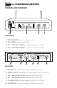
364110806500
ANTENNA -A ANTENNA -B
DC13~18V
500 mA
RISK OF ELECTRIC SHOCK
DO NOT OPEN
Taking apart or mo dif ying
the re ceiver may lead to
electric s hock , fire, or
damage t o the r eceiver and
will void your warranty.
MIC 2 BALA NC ED MIC 1 BALA NC ED
TRUE DIVERSITY
MIX
MIC 1 & 2
UNBAL AN CED
AUDIO OUTPU T DC-POWER
Better Mu sic Builder
®
®
Mod el No.: VM-52U G 2
(UHF Microphone)
CALIFORNI A, UNITED STATES OF AMERICA
E-MAIL: s ales@bett ermusic builder.com
w ww .B et te rM us ic Bu ild er .c om
ENGINEERED AND DE SIGN IN U.S.A.
SERIAL NO.:
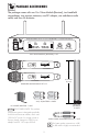
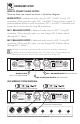
HARDWARE SETUP
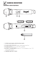
HOW TO CONNECT AUDIO OUTPUT:
There are three rear outputs as shown in the below diagram:
MIXED OUTPUT is unbalanced audio output for MIC 1 & MIC 2 using 1/4”
connection. When using this output, MIC 1 and MIC 2 have to share a signal. To
produce different effects on each microphone, MIC 1 and MIC 2 need their own
signals which can be done by using XLR connections.
MIC 1 BALANCED OUTPUT is balanced audio output for MIC 2 using XLR
connection. When using this output, you can change MIC 2 effects without
affecting MIC 1 effects.
MIC 2 BALANCED OUTPUT is balanced audio output for MIC 2 using XLR
connection. When using this output, you can change MIC 2 effects without
affecting MIC 1 effects.
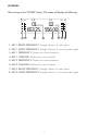
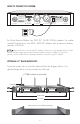
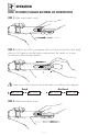
UHF WIRELESS SYSTEM DIAGRAM:
Set Up
We highly recommend using balanced XLR connections if the distance between the
microphone receiver and the amplifier/mixer is more than 10 feet. The grounding of the
balanced XLR connection delivers better quality signal by reducing noise.
Recommend
BALANCED CONNECTION
5
AUDIO MIXER AMPLIFIER OR A KARAOKE UNIT INPUT TERMINAL
REAR VIEW
1
MIXED OUTPUT
(MIC 1 & 2 UNBALANCED)
2
MIC 2 BALANCED OUTPUT (BALANCED XLR)
MIC 1 BALANCED OUTPUT (BALANCED XLR)
3
ON
UHF WIRELESS SYSTEM VM-52U G2
MIC 1 HANDHELD MICROPHONE
ON
UHF WIRELESS SYSTEM VM-52U G2
MIC 2 HANDHELD MICROPHONE